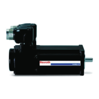
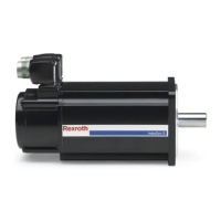
The shaft load diagrams of the individual motors are given in the following
chapters:
● MKE037 chapter 4.2 "MKE037" on page 26
● MKE047 chapter 4.3 "MKE047" on page 28
● MKE098 chapter 4.4 "MKE098" on page 30
● MKE118 chapter 4.5 "MKE118" on page 33
Maximum permissible radial force
Fradial_max
The maximum permissible radial force F
radial_max
depends on the following fac‐
tors:
● Shaft break load
● Force's point of application x
● Shaft design (plain; with key)
Permissible radial force Fradial
The maximum permissible radial force F
radial
depends on the following factors
● Arithmetic mean speed (n
mittel
)
● Force's point of application x
● Bearing lifetime
Permitted axial force Faxial
The maximum permitted axial force F
axial
is specified in the Technical Data, in
the ”Shaft load” section.
Mean speed
In the exact calculation of the mean speed according to the following example,
the run-up and braking times are taken into account.
n
1m
; n
2m
Mean speed section
n
1
; n
2
processing speed
t
H1
; t
H2
run-up time
t
1
; t
2
processing time
t
B1
; t
B2
braking time
t
11
; t
22
standstill time
Fig.9-18: Mean speed
A complete processing cycle can consist of several sections with different
speeds. In this case, the average is to be generated from all the sections.
The run-up and braking times can be ignored in the calculation if
the time in which the drive is operated at a constant speed is sig‐
nificantly greater than the acceleration and braking time.
9.10.3 Attachment of Drive Elements
Whenever attaching drive elements to the output shaft, such as
● gearboxes
Project Planning Manual | Rexroth MKE Synchronous Motors Electric Drives
and Controls
| Bosch Rexroth AG 87/131
Operating Conditions and Application Notes

 Loading...


