About this documentation 5/24
RE 66170-10-R/2019-05-15, control block SB24/34, BoschRexrothAG
1.3 Representation ofinformation
Uniform safety instructions, symbols, terms and abbreviations are used throughout
this documentation toensure safe and proper use ofthe product. For clarification,
they are explained inthe sections below.
1.3.1 Symbols
The following symbols indicate information that isnot safety-relevant but increases
understanding ofthe documentation.
Table 2: Meaning ofsymbols
Symbol Meaning
Ifthis information isdisregarded, the product cannot beused and/or
operated toits full extent.
▶
Single, independent action
1.
2.
3.
Numbered instruction:
The numbers indicate that theactions must becompleted inorder.
Black circle with white number:
Auxiliary marking forabetter understanding.
White circle with black number: Position orassembly group with
reference tothe parts list and tothe graphics within achapter.
White circle with black letters: Assembly group with reference tothe
parts list and tothe graphics within achapter.
1.3.2 Designations
This documentation uses the following designations:
Table 3: Designations
Designation Meaning
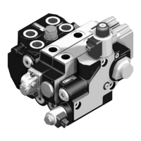
SB24-M Control valve with mechanical control
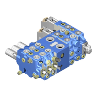
SB24-EHS/SB34-EHS Control valve with CAN bus-controlled electrohydraulic actuating unit
EHR24-EHS Control valve with CAN bus-controlled electrohydraulic actuating unit
forelectrohydraulic hitch control
EHR24-EM2 Control valve with PWM signal control for electrohydraulic hitch control
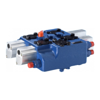
Control valve Directional valve type SB
Hitch control valve Directional valve type EHR

 Loading...
