8/24 About these products
BoschRexrothAG, control block SB24/34, RE 66170-10-R/2019-05-15
4 About these products
To ensure clear presentation ofthe control block assembly / disassembly, the
representation ofthe control block segments has been simplified and/or reduced
tothe essential and summarized indummies.
The work steps are described based onacontrol block with dummy block
segments.
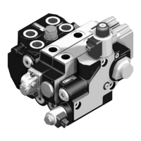
4.1 Overview ofcontrol block segments
Plates
▲ End plate (EP) ▲ Connecting plate (AP)
Directional valves
▲ End valve (EVL) ▲ Standard directional valve (SVL) ▲ Hitch control valve EHR24-EM2
4.2 Tie rod bores and threads
The control block segments are clamped together bymeans oftie rods and nuts.
For this purpose, the control block isprovided with threaded bores atone control
block segment and the following control block segments are provided with through
bores inthe flange surfaces.
At the final control block segment, the tie rods protrude atthe end surface.
Onthe protrusion, the tie rod nuts are located.
Example:
Bore Bore Bore Bore Thread
Nut EP / EVL SVL SVL SVL AP
 Loading...