30
CN902
CN903
TP704
Changer PCB
TP701
PT821
TP823
TP824
FE
V+
GND
1/2 V
CC
F 1.75kHz
T 2.15kHz
X
Y
SCOPE
CD20
ALIGNMENT
FIXTURE
CD-A
CD-B
POWER
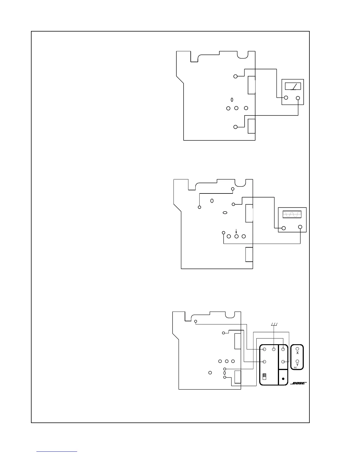
Figure 2. Tracking Balance Alignment
Figure 3. Focus Gain Alignment
CN902
CN903
TP704
PT824
TP824
_
+
DC Voltmeter
Changer PCB
ATSC
Figure 1. FE Bias Alignment
Note: The CD changer must be placed into
a CD-20 music center for the following
procedures. The CD changer cannot be
operated by itself.
Equipment Needed
1. CD-20 Alignment Fixture (P/N: 191749)
2. Oscilloscope
3. DC Voltmeter
4. Test CD (A•Bex TCD-784) or equivalent.
Note: Remove the solder from the location
ATSC before performing any alignments.
Perform these procedures in exact order!
1. FE Bias Alignment
1.1 Connect the power pack to the CD-20
and leave the CD-20 in the OFF mode.
1.2 Connect a DC voltmeter to TP824 (FE
out) and TP704 (1/2 Vcc). See Figure 1.
1.3 Adjust the potentiometer PT824 until
the meter reads < 10mVdc.
2. Tracking Balance Alignment
2.1 Insert the CD A•Bex TCD-784 and play
track number seven.
2.2 Connect TP601 (TEST) to TP705
(GND). See Figure 2.
2.3 Remove the solder from the points
labeled SLED and then TRACK.
2.4 Connect an oscilloscope to TP822 (+)
and TP704 (-).
2.5 Adjust PT823 (T.BAL) until the wave
form is symmetrical about 0VDC, V1=V2.
See Figure 5.
2.6 After the adjustment is done, solder the
points labeled TRACK and SLED. Remove
the connection from TP601 (TEST) to
TP705 (GRN).
ALIGNMENT PROCEDURES
Changer PCB
CN902
CN903
TP704
PT823
TP822
_
+
Oscilloscope
TP705
TP601
Sled
Track