8
THEORY OF OPERATION
1.0 Overview
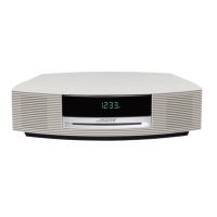
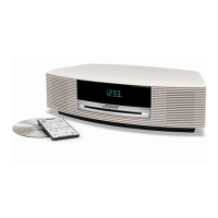
The CD-20 is a self-contained CD player with a 6-disc changer, AM/FM tuner, preamplifier, and
control center for use with Bose
®
powered speaker systems. In addition to the two internal
sources (CD and tuner), it allows for up to four external audio sources to be connected (Tape,
Aux, Video 1 and Video 2). It uses an RF remote control, allowing it to be operated from differ-
ent rooms within a house without the line-of-sight restrictions of an IR remote. No CE-1 type
functionality has been included. All Smart Speaker data commands (i.e.-for AM-25P) have
been implemented.
The CD-20 has two independent output zones, similar to CD-10, accessible through circular
DIN connectors in the back of the product. This allows Zone 1 to play any of the six possible
audio sources, while Zone 2 plays the same source (or any other audio source) simulta-
neously. The only restriction is that AM and FM cannot be played simultaneously (there is only
one tuner source, usable in only AM or FM mode at a given time).
2.0 Power Supply Electronics (Schematic Diagram Sheet 1)
The unit is powered by an external 12 VAC power supply capable of delivering 1.6 Amps RMS.
D12, D1 and C3 form a positive half-wave rectifier that supplies voltage to the CD_VCC regu-
lator transistor Q10 (which powers the CD mechanism). Feedback components R23, D13 and
R24 sample the CD output voltage, divide it down, and apply it to Q11's emitter. Q11 keeps
Q10 turned on until the CD_VCC voltage reaches the desired level. Once CD_VCC reaches
about 14.5 volts, Q10 goes linear and keeps the output voltage from going any higher. To
disable the CD_VCC supply, the CD_RES line is set to +5V by the microprocessor, which turns
Q1 and Q2 on. Q1 keeps Q11 turned off, while Q2 quickly shorts CD_VCC to ground (turning
the CD mechanism off immediately).
R2, D4 and C6 form a positive half-wave rectifier that supplies voltage to +5V regulator IC U1.
The +5V circuit powers the microprocessor and EEPROM. The microprocessor monitors the
DETECT line (via comparator U402) in case of a power failure.
D5 and C10 form a positive half-wave rectifier that supplies voltage to +10V regulator IC U2.
The +10V supply powers all the audio circuitry, the tuner, and the enable lines for the external
powered speakers.
C24, R28, R29 and C21 form a resistor/capacitor AC voltage divider that provides the 4.2 VAC
for the VFD (display) filament. The -30 Vdc and -24 Vdc supplies are also for the VFD, and are
generated using a negative voltage tripler. D6, D9, D7, C15, C23, and C18 form the tripler. R11
and zener diode D18 regulate the tripled voltage to -30V. The -24 Vdc supply is divided down
from the -30 Vdc by R26, R12 and R14.
The enable lines (also referred to as +10V control lines) for the powered speakers (Z1_ENBL
and Z2_ENBL) are powered by Q102 and Q104. Q101 and Q103 provide base turn-on current
when the microprocessor sets Z1_ENBL or Z2_ENBL to +5V. The output of the enable lines is
current-limited to less than 100 mA by R134 and R138. This protects against accidental short-
circuits in the speakers or their cables.