39
DISASSEMBLY PROCEDURE
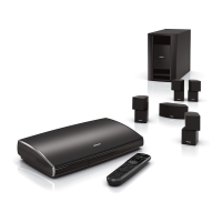
3.2 Incline the Power stand to let the I/O
panel assy go downwards as indicated in
Figure 12.
Note: Be careful the I/O panel assy is very
heavy.
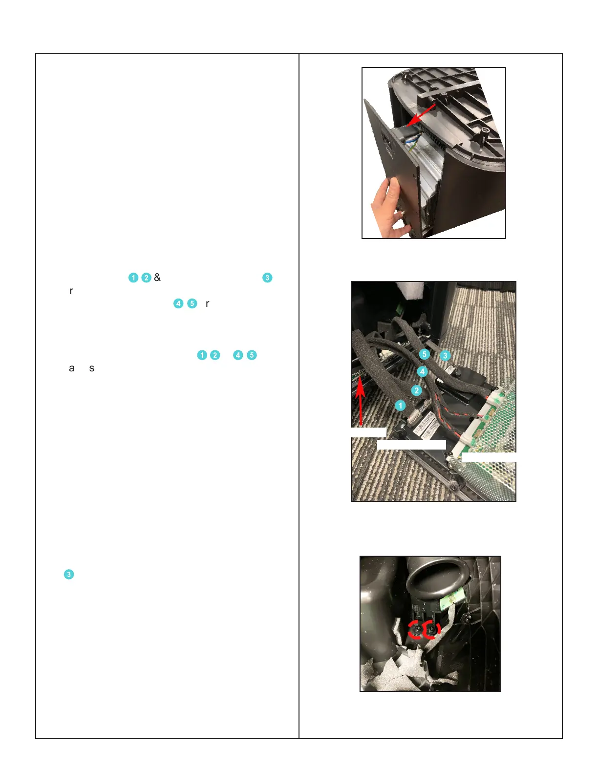
3.3 Once the I/O panel assy is out from the
Enclosure, you will notice that the 2 Volume
board cables
1
2
& the 1 Antenna cable
3
are attaching the Main-I/O board and the 2
Transducer harnesses
4
5
are attaching the
Power & Amp Board. Figure 13.
3.4 Remove the green adhesive with IPA
(Isopropyl alcohol) from the
1
2
&
4
5
cables' connections with Main-I/O board &
Power-Amp board .
Note:
• Use a spudger / screwdriver to separate the
green adhesive from the edge of connections.
• Be careful when regluing the green adhesive
to x the connections.
Re-assembly Note:
• RTV may be used if the green adhesive is
not available.
3.5 Detach all the board cables from Main I/O
board & Power-Amp board except the cable
3
. At this time, it can be detached only by the
other end of the connection. Figure 14.
Figure 13. Main-I/O Board & Power-Amp
Board Cables
Figure 14. Antenna Board Screws Removal
Main-I/O Board
Power-Amp Board
Volume Board
Figure 12. Incline the Power Stand

 Loading...