35
DISASSEMBLY PROCEDURE
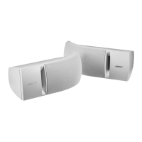
1.4 Use your hands and lift up on the
Bottom Cover as indicated in Figure 7.
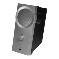
1.5 Once the Bottom Cover is out from the
Top Cover, you will notice that the 2 cables
1
3
& the 1 FFC cable
2
are attaching the
Main-I/O board from Air fan bae and Pow-
er-Amp Board. Figure 8.
Re-assembly Note:
If the Ferrite bead is in the position as indi-
cated in Figure 8 (left), unwrap the adhesive
foam and move it to the position Figure 8
(right) to not get wedged in between the plas-
tic fan housing and any electrolytic capacitors
on the board when reassembling.
2. Main-I/O Board Removal
2.1 Perform procedure 1.
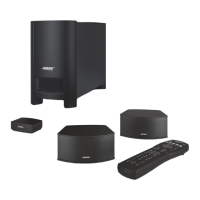
2.2 Remove the green adhesive with IPA
(Isopropyl alcohol) from the
4
5
cables'
connections with Volume board. Figure 9
2.3 Remove the green adhesive
3
holding the
Bluetooth antenna cable and disconnect the
Bluetooth antenna connector as the red arrow
indicated in Figure 9.
2.4 Remove the 7 screws securing the Main-
I/O board. Figure 9.
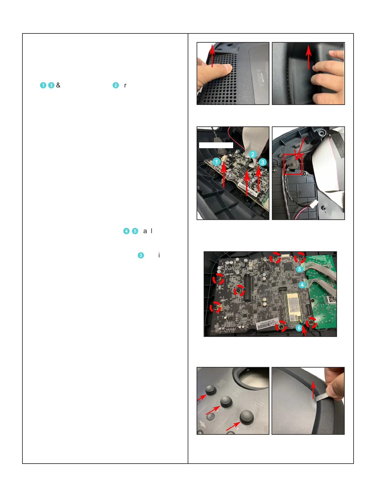
2.5 Pull the 3 Volume knobs out. Figure 10
(left).
2.6 The PC sheet top cover are secured with
Pressure Sensitive Adhesive - use a spudger,
lift the Top cover up and grasp and pull them
o. Figure 10 (right).
Note: Use a heat gun, gently heating the
whole top surface moved around the area to
help loose the adhesive.
Re-assembly Note:
Use a new replacement PC sheet top cover to
ensure proper adhesion during reassembly.
PN: 843967-0110
Figure 7. Bottom Cover Removal
Figure 8. Detach Cables Connection & Ferrite
Bead Position
Figure 9. Main-I/O Board Green Adhesive &
Screws Removal
Figure 10. Volume Knobs & Top Cover
Removal
Ferrite Bead

 Loading...