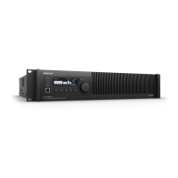
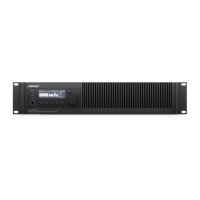
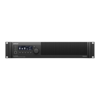
11
Basic Setup Using Front Panel Controls
Upon initial power-up of the unit, all front panel LED indicators will illuminate during firmware
loading and testing. After about 20 seconds, the LCD will display the default screen from which
the Main Menu may be accessed to make changes to the Factory Default Settings.
LCD Operation Screen (no signal) - 4 channel units are similar
Front Panel Menus and Default Configuration
The following table shows the front-panel menu structure and factory default settings:
Factory Default Settings with Default Input-Output Matrix Mixer Attenuation
(note: -0 dB is full signal)
CH
1
CH
2
CH
3
CH
4
CH
5
CH
6
CH
7
CH 8
IN A
- 0
dB
off off off off off off off
IN B off
- 0
dB
off off o ff off off off
IN C off off
- 0
dB
off off off off off
IN D off off off
- 0
dB
off off off off
IN E off off off off
- 0
dB
off off off
IN F off off off off off
- 0
dB
off off
IN G off off off off o ff off
- 0
dB
off
IN H off off off off o ff off off
- 0
dB
UTILIT Y
Standby Mode not in standby
Fault log empty
Lock Front Panel off
Set Front Panel Lock 0-0-0-0-0
Display Normal (brig ht)
Net work setup (N) Fixed IP
Network address (N) 192.168.0.80
LEVEL
Output Mutes Off
Output Attenuate - 0.0 dB
Input Mute Off
Input sensitivity +12 dBu
Input Source Analog
Meters
Output dB scale
Input dB scale
DSP
Speaker presets none
Array EQ Off
Input PEQ On - flat
Output PEQ On - flat
Delay 0 mSec
Limiting - Peak 89.0 V
Limiting - RMS 45.0 V
Limiting RMS - Attack 1000 mS
Limiting RMS - Release 2000 mS
CONFIGURATION
Output Config mono
Input Routing CH 1 see table

 Loading...
