85
TEST PROCEDURE
6. Signal LED Test
6.1 Apply a -50.2 dBV +/- 2 dBV, 1 kHz sine wave to the channel 1 - 4 EURO BLOCK connectors. Verify
that the SIGNAL LED lights GREEN.
6.2 Change the input level to +6.8 dBV +/- 2 dBV. Verify that the SIGNAL LED lights AMBER.
6.3 Change the input level to +9.8 dBV +/- 2 dBV. Verify that the SIGNAL LED lights RED.
7. Limit LED Test
7.1 Apply a + 2.0 dBV +/- 2 dBV, 1 kHz sine wave to the channel 1 - 4 EURO BLOCK connectors. Verify
that the LIMIT LED lights AMBER.
8. Crosstalk Test
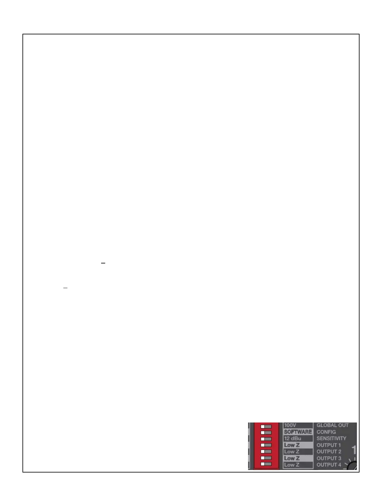
8.1 Set the Output 1 - 4 DIP switches to Hi-Z mode (left). Set the GLOBAL OUT DIP switch to 100V
(right). Set the SENSITIVITY DIP switch to 4 dBu (left). All other DIP switches should be set to the left.
8.2 Connect 32 Ohm, 250W loads to the channel 1 - 4 outputs.
8.3 Using a 20 Hz to 20 kHz lter, apply a 1 kHz, -19.3 dBV input to the channel 1 input jack.
8.4 Adjust the input signal level to get a 100W output at the channel 1 output.
8.5 With the above input applied to the channel 1 input, measure the output level at the channel 2, 3 and
4 outputs. It should be > -70 dB.
8.6 Change the input frequency to 20 kHz. Measure the output level at the channel 2, 3 and 4 outputs. It
should be > -55 dB.
8.7 Repeat steps 8.3 to 8.6 for the channel 2, 3 and 4 inputs.
AmpLink Functionality Tests
Required Items:
• Audio Precision ATS-1 or equivalent
• Audio Precision AUX-0025 digital lter or similar
• Windows PC with Bose
®
ControlSpace
®
Designer version 5.0 or greater installed
• Bose ControlCenter CC-1, part number 768932-0110 or similar
• Bose ControlSpace ESP-880 digital processor or other AmpLink source, i.e. CS EX-1280C
• dB Meter
• 4 - 4 Ohm, 250W load resistors
• 4 - 16 Ohm, 250W load resistors
• 4 - 32 Ohm, 250W load resistors
UUT Switch Settings:
Set the PS404A or PS604A rear panel controls as listed below for
following tests.
• Analog Input Select Rotary Switch to position 1, 1:1
• Rotary EQ switch to position 1 FLAT
• Output Trim 1 - 4 to MAX (fully CW)
• DIP switch setting: all switches to LEFT