15
DISASSEMBLY PROCEDURES
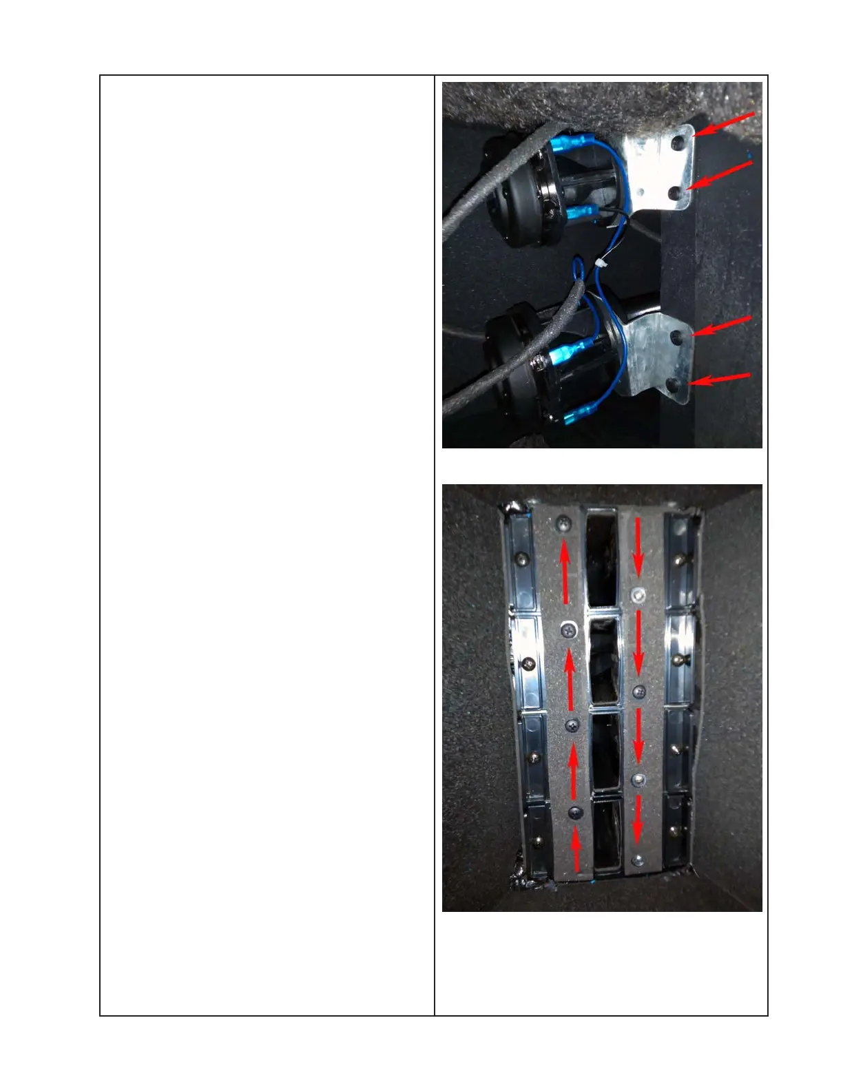
Compression Driver Screw Locations
5. Compression Driver Removal
5.1 Perform procedure 4 to remove the
woofers.
Notes:
• It is necessary to remove at least one of the
woofers in order to gain access to the
compression driver/waveguide subassem-
blies.
• Each compression driver is mounted to its
own waveguide. The waveguide/compres-
sion driver subassemblies are each remov-
able separately.
5.2 Remove the two screws that secure
the compression driver/waveguide subas-
sembly you wish to remove to the inner wall
of the enclosure. See photo at right.
5.3 Remove the two screws on the front of
the enclosure that secure the waveguide for
the compression driver that you wish to
remove. These screws will be diagonally
across from each other. Be sure to support
the weight of the subassembly when remov-
ing the final screw.
5.4 Once the screws are removed, rotate
the compression driver/waveguide subas-
sembly out of the enclosure through the
woofer opening.
5.5 Disconnect the two Faston connections
from the compression driver.
5.6 Remove the two screws that secure the
compression driver to the waveguide. Lift
off the compression driver. Be sure to retain
the screws and other hardware for re-use.
Waveguide Screw Locations
 Loading...