16
DISASSEMBLY PROCEDURES
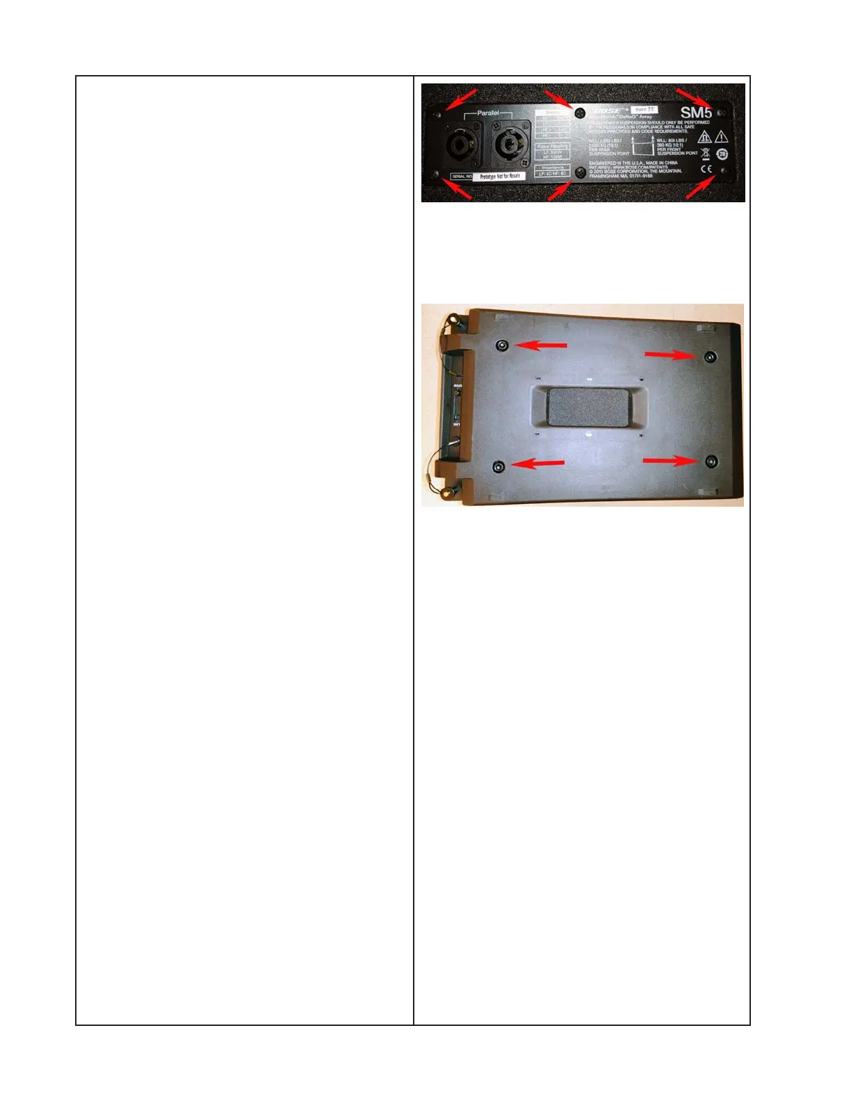
6. Input/Output Panel Removal
6.1 Remove the six screws that secure the
I/O panel to the enclosure. Lift off the I/O
panel.
6.2 Make a note of the wiring configuration
and disconnect the wiring harness from the
I/O panel.
7. End Cap Removal
7.1 Remove the four hex head cap screws
that secure the end cap (31) to the enclo-
sure. Lift off the end cap.
Re-assembly Note: When re-installing end
caps, torque screws to 5.0 +/- 0.25N-m
(43 +/- 2 in-lbs).
CAUTION: The Front Rigging Assemblies
(28, 29) and Rear Rigging Sub-assemblies
are not removable due to safety concerns.
Do not attempt to remove them from the
enclosure.
Input/Output Panel Screw Locations
Endcap Screw Locations
 Loading...