16
Assembly, Part Two– chassis wiring
OK, time to fire up your soldering iron!
WHOA! Soldering lesson!
Whenyoureadtheword“attach” inthis manual,it meanstoinserta wireleadthroughaterminal
strip hole, and wrap it around the outside of the terminal. Needlenose pliers are the trick here. The
ideaistocreateamechanicallysoundconnection.Ifyoucan’twrapthewirecompletelyaroundthe
solder point, at least bend it so that it will hold its position while being soldered. Don’t solder the
connection until instructed to in the manual, as other leads may attach to the terminal later.
Most of all, remember that the soldering iron is a hot item! The tip temperature can approach 800
degrees,andwon’tfeeltoogoodifyouabsentmindedlytouchit!(Thinkofasteakhittingthehotgrill
of your BBQ...)
When the instruction is given to solder the terminal use the following procedure:
Apply the tip of the iron to contact both the terminal and the lead(s) attached, and let it rest
against the joint long enough to heat the terminal thoroughly.
Flow enough solder onto the joint to fill the joint between the terminal and every lead attached to
it. Look for a concave fillet of solder at each junction rather than a convex blob of solder.
Be sure to touch the solder to the hot joint, not the tip of the iron.
Remove the iron and let the joint cool unassisted (don’t blow on it!). A joint which cools too
quicklyormoveswillbecome“cold”,itwillcrystallizeandcooltoadullfinish.Acoldjointwillnot
function structurally, nor will it conduct properly. Reheat any cold joints, applying a small
additional amount of solder, and make sure that it cools to the proper shiny finish.
Keep the tip of the soldering iron clean. A slightly damp sponge is the tip cleaning tool of choice.
Terminal convention
There are several types of solder terminals in this kit. The terminals on the tube sockets are grouped
by a letter designation. The nine pin socket terminals are labeled A1 through A9. The octal socket is
labeled B1 through B8. Note—the terminal designations (numerals only) are also molded into the
ceramic bottom of each socket. The power transformer terminals are noted on the label, and the ter-
minalnumbersarealsomoldedintotheplasticnexttoeachterminal.The“L”(live),“N”(neutral)and
“E”(earthorsafetyground)designationsoftheIECpowerentrysocketarealsomoldedintothe
plastic next to each terminal.
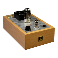
The phenolic terminal strips have terminals assigned 1 through 22. We strongly suggest marking
these designations on the chassis plate with a fine tipped Sharpie, referring to the photo on page 15.
IMPORTANT: each of the terminals on the terminal strips and the octal tube socket has an upper
hole and a lower hole. We will use both sets of holes to reduce the number of wires attached to each
hole. In the following wiring instructions we will use a U or an L to designate whether the wire is at-
tached the upper or lower hole. For example terminal 1U would mean attach the wire to the upper
hole of terminal strip terminal 1, B7L would mean attach the wire to the lower hole of octal socket ter-
minal B7.