27
B+ supply component orientation
The B+ or high voltage supply uses a full wave bridge type power supply. The orientation of the
bands and stripes of the rectifier diodes and filter capacitors is absolutely critical. Refer to the
photos for proper orientation of the components.
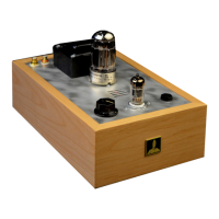
Full Wave Bridge
()BendtheleadsofaUF4007rectifier3/8”(9mm)from
the rectifier body. With the rectifier located on the side of
the terminal strip nearest the power transformer, attach
the black end to 20L and attach the banded end to
terminal 18L.
( ) Bend the leads of the second UF4007 rectifier with
leads1/2”(12mm)fromtherectifierbody.Linetherectifier
body up over the first one on the same side of terminal
strip, with the black end attached and soldered to terminal
18L and the banded end attached to terminal 21L. Trim
excess leads from18L.
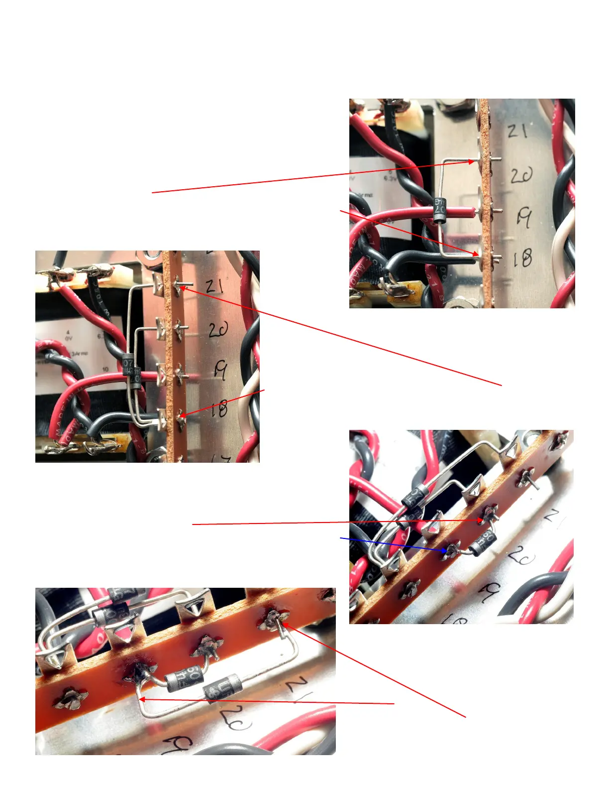
( ) Bend the leads of a third UF4007 rectifier close to the
rectifier body. With the rectifier located on the side of the
terminal strip away from the power transformer, attach the
black end to 20L and attach the banded end to
terminal 19L.
Solder and trim excess leads from 20L.
( ) Bend the leads of a fourth UF4007
rectifier3/8”(9mm)fromtherectifierbody.
With the rectifier located on the side of the
terminal strip away from the power
transformer, attach the black end to 19L
and attach the banded end to terminal 21L.
Solder 19L, 21L and trim excess leads.