21
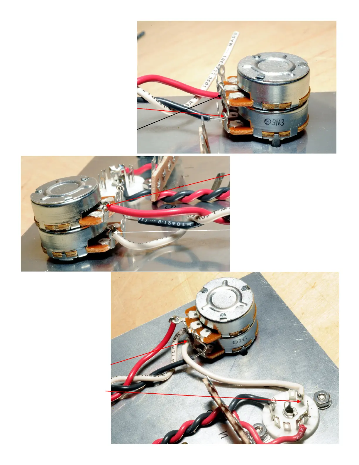
Attenuator Wiring
The braided wire you have installed
connects the left and right audio
signals coming from the input jacks
to the potentiometer attenuator,
a.k.a the volume control.
()Strip1/2" (12mm)ofinsulation
from the free end of the black wire.
Thread the bare end through the
inboard potentiometer terminal
closest to the chassis plate, then
through the terminal directly above
that(thatis,“above”withthe
chassisinverted).Don’tsolderyet.
()Trim1”(25mm)fromfreeend
oftheredwire.Strip1/4”(6mm)
of insulation from end and attach
the bare end through the
outboard potentiometer terminal
farthest from the chassis plate.
Solder.
()Trim1/2”(12mm)fromfree
end of the white wire. Strip
1/4”(6mm)ofinsulationfromend
and attach the bare end through
the outboard terminal closest to
the chassis plate. Solder.
Now you will connect the
attenuator to the grids of
the input tube.
()Cuta3”(75mm)piece
of white wire and strip both
ends1/4”(6mm).
Attach and solder one end
to the center terminal of the
potentiometer that is
closest to the chassis plate.
Attach and solder the other
end to nine pin socket
terminal A2.