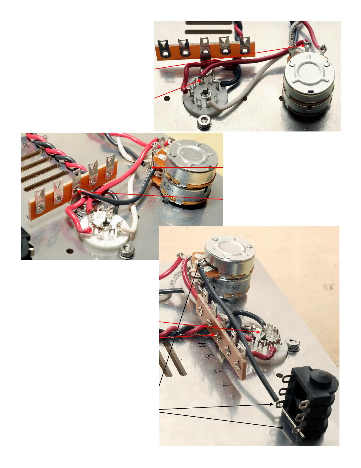
22
( ) Cut a 2-3/4”(70mm)pieceofredwire
andstripbothends1/4”(6mm).
Attach and solder one end to the center
terminal of the potentiometer that is
farthest from the chassis plate. Attach
and solder the other end to nine pin
socket terminal A7.
( ) Cut a 2-1/2”(62mm)pieceof
black wire and strip both ends
1/4”(6mm).
Attach and solder one end to the
inboard terminal of the
potentiometer that is closest the
chassis plate. Attach the other end
toterminal3L,butdon’tsolder.
( ) Cut a 2-1/4”(56mm)pieceofblackwire
andstripbothends1/4”(6mm).
Attach one end to the center terminal of
theninepintubesocketA.Don’tsolder.
Attach the other end to terminal 3L and
solder.
( ) Cut a 4-1/2”(112mm)pieceofblack
wire.Striponeend1”(25mm)andstripthe
other1/4”(6mm).
Attachandsolderthe1/4”strippedendto
the inboard terminal of the potentiometer
that is farthest from the chassis plate.
Insertthe1”strippedendthroughthetwo
TRS phone jack terminals closest to the
chassis(the“S”oftheTRS),butdon’t
solder.