121
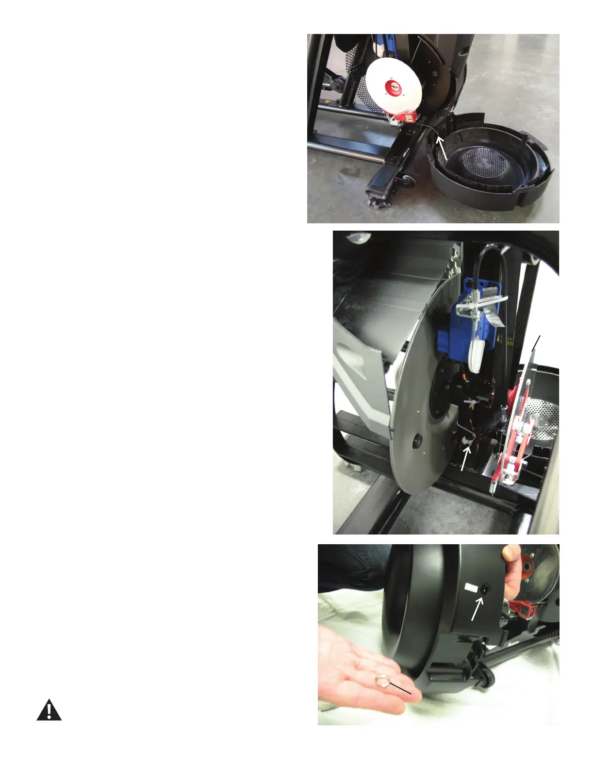
5. Disconnect the Power Inlet from the Power Connector behind the
Brake Disc.
6. Using a 15mm open end wrench, remove the Securing Ring from
the outside of the Right Fan Cover.
7. Remove the Power Inlet from the inside of the Right Fan Cover.
8. Installation is the reverse procedure.
9. Final Inspection
Inspect your machine to ensure that all hardware is tight and compo-
nents are properly assembled.
Do not use until the machine has been fully assembled
and inspected for correct performance in accordance
with the Owner’s Manual.
Power Inlet
Securing Ring
Power
Connector
Brake
Disc
Power Cable