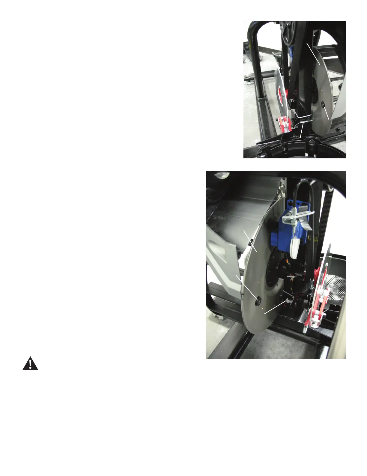
136
Note: Left Fan Cover is hidden for image clarity.
5.Usinga#2Phillipsscrewdriver,removethescrewthatattaches
the Speed Sensor.
Note: To assist with re-assembly, note that the new Speed Sensor
must be 3mm (1/8”) from the Speed Sensor Magnet on the Fan Disc.
6. Disconnect the Speed Sensor Cable noting how it was routed for
re-assembly.
Note: Do not crimp the Cables.
7.Usinga#2Phillipsscrewdriver,attachthenewSpeedSensor.Be
sure to place it 3mm (1/8”) from the Speed Sensor Magnet on the
Fan Disc.
8. Route the new Speed Sensor Cable under the bracket and con-
nect the cable.
9. Installation is the reverse procedure.
10. Final Inspection
Inspect your machine to ensure that all hardware is tight and compo-
nents are properly assembled.
Do not use until the machine has been fully assembled
and inspected for correct performance in accordance
with the Owner’s Manual.
Speed
Sensor
Speed Sensor
Cable
Speed
Sensor
Magnet
Fan Disc
Fan Disc
Speed
Sensor
Magnet