146
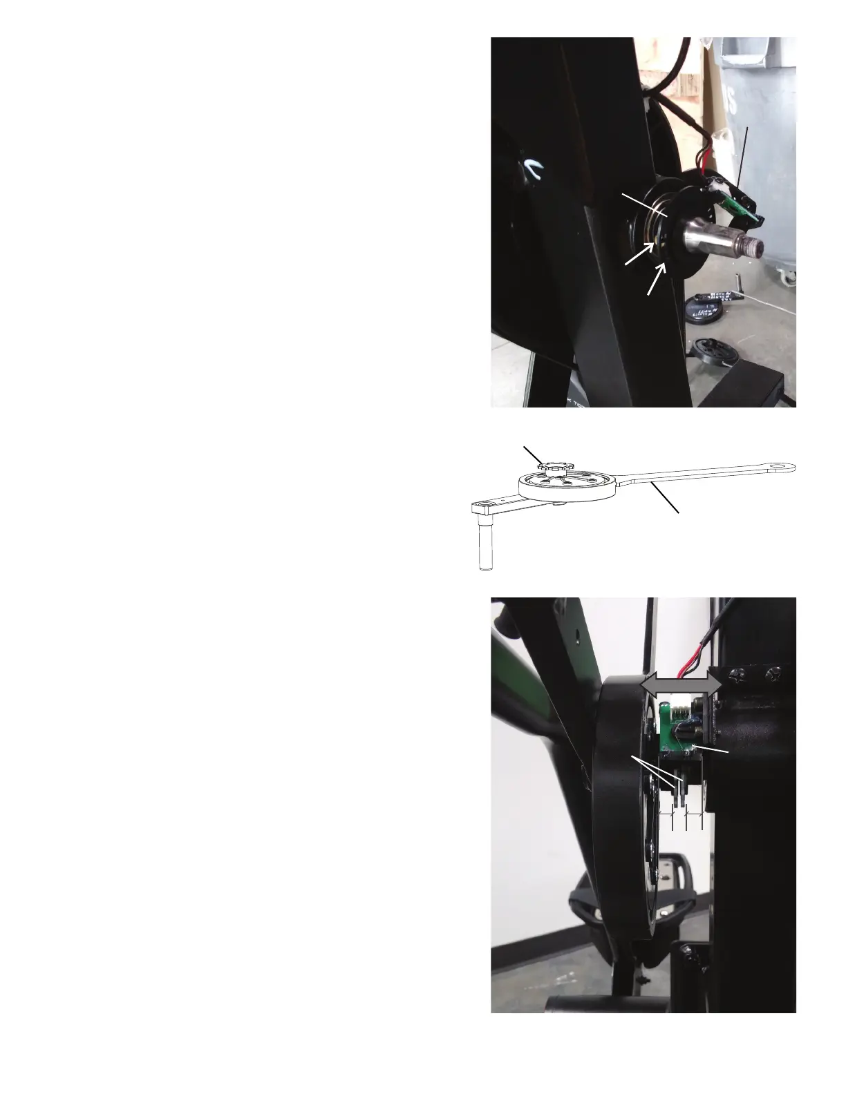
Note: The image shows a properly installed Upper Body
Sensor. Shrouds are removed for clarity.
Upper Body
Sensor
=
Codewheels
Right Crank Arm
Outer Codewheel
25. Using a 2mm hex wrench, loosen the two screws (indicated by ar-
rows) that secure the Inner Codewheel Assembly.
26. After noting the orientation of the Inner Codewheel Assembly on the
axle, remove the old Inner Codewheel Assembly. Replace with the new
Inner Codewheel Assembly so it is in the same orientation.
27. Using the 2mm hex wrench, tighten the two screws that secure the
Inner Codewheel Assembly.
28. Slide the Right Crank Arm Assembly onto the machine.
Note: Be sure not to damage or break the Outer Codewheel on the Right
Crank Arm or the one still remaining on the machine.
29. Re-attach the Upper Body Sensor so that it is centered on the Outer
and Inner Codewheels.
30.WiththeUpperBodySensorcenteredontheCodewheels,conrm
that the Upper Body Sensor does not rub anything by using the machine
briey.AdjusttheUpperBodySensorasnecessary.
Inner Codewheel
Assembly
Upper Body
Sensor