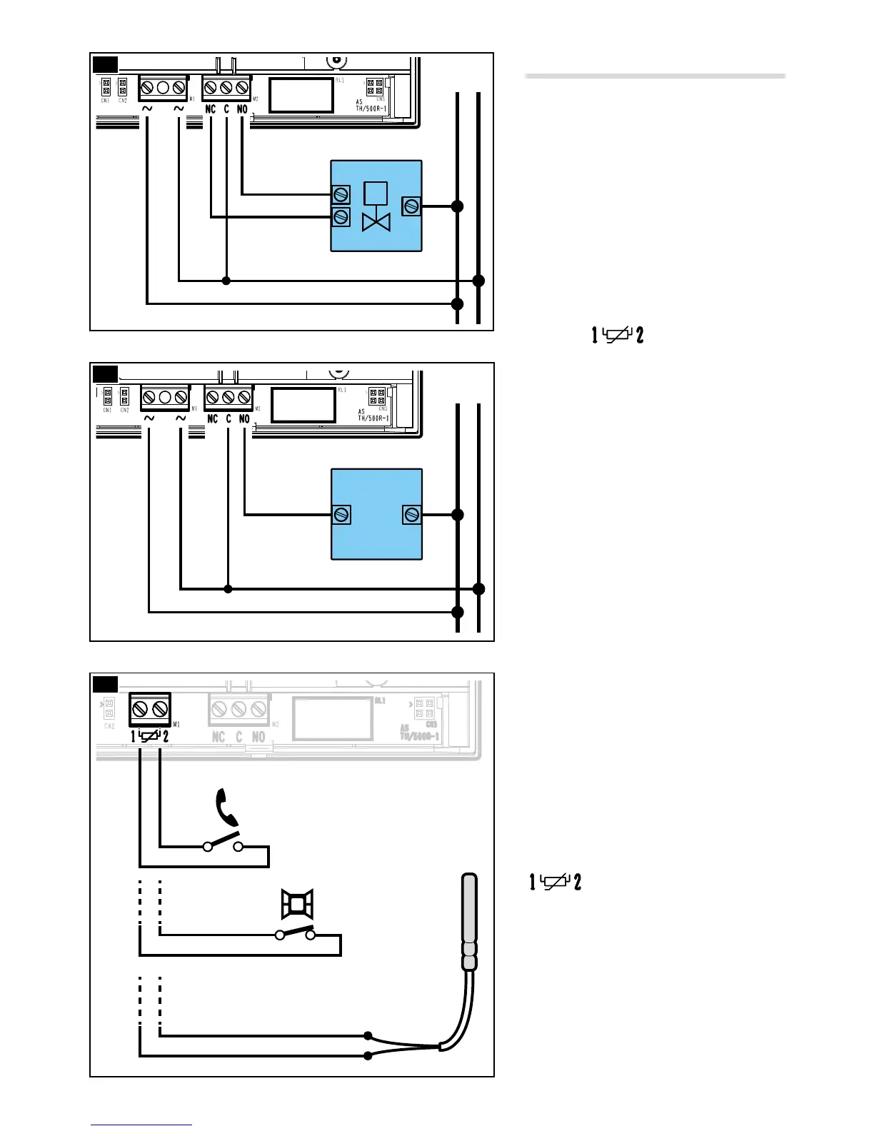
Electrical connections.
The connections are made according to
the type of equipment controlled by the
programmable thermostat.
Figures D and E refer to the
mains-powered programmable thermo
-
stat but are also valid for the battery-pow-
ered version, only for the part relating to
the relay contacts.
Figure F illustrates possible uses of the
terminals
present only on the
battery-powered model.
① Connection through remote activation
(maximum distance 20 metres),
② Connection through magnetic contact
(maximum distance 20 metres),
③ Connection by remote probe (OH/STI,
OH/STE, maximum distance 10 metres),
KEY
Mains power supply wires
N = neutral – L = live
Relay contacts
NC = normally closed contact
C = common
NO = normally open contact
Loads
U1 = burner, circulation pump, solenoid
valve, etc.
U2 = motorised valve
Inputs for remote control
(only on battery-powered model)
NOTE. Before connecting, refer to the
technical documentation of the device
to be controlled.
VALVE
LOAD
U1
OPEN
CLOSED
U2