36
BRAKE VALVE SERVICE
Most CH Series hoists are supplied with our BRADEN
1.5-inch brake valve. It is a reliable hydraulic valve with
internal components manufactured to close tolerances.
Due to these close tolerances, several individual parts
are not available as replacement parts and are noted in
the following parts lists as not serviced separately (NSS).
Before disassembling the brake valve, be sure you have
conducted all applicable troubleshooting operations and
are certain the brake valve is causing the malfunction.
Thoroughly clean the outside surfaces of the valve and
work in a clean dust-free area, as cleanliness is of utmost
importance when servicing hydraulic components.
1.5-inch brake valves built after mid-March 1997 contain
a spring seat (Item 22) between the spool spring and the
spool. This provides a slightly larger, more uniform area
for the spring to seat against the spool. The result is in-
creased spring service life and improved repeatability of
pressure/ow modulation over the full compression range
of the spring.
The spring retainer has been modied to allow for the
additional thickness of the spring seat and a groove ma-
chined into the hex end cap serves as a visual indication
that the valve contains the new spring seat. The spring
seat improvement may be added to earlier brake valves
by installing kit, Part Number 62805. Items 3, 7, 13, 14
and 22 are included in the kit. We recommend that this
kit be installed whenever the brake valve is removed for
inspection or service.
It is always a good practice to check the initial opening or
cracking pressure of the brake valve whenever the hoist
is serviced or inspected. Refer to BRADEN Service Bul-
letin 527 for complete brake valve test and adjustment
procedures.
12
2
1
14
19
4
5
15
18
17
16
21
3
13
14
6
7
8
22
20
11
19
10
12
2
1
14
19
4
5
15
18
17
16
21
3
13
14
6
7
8
22
20
11
19
10
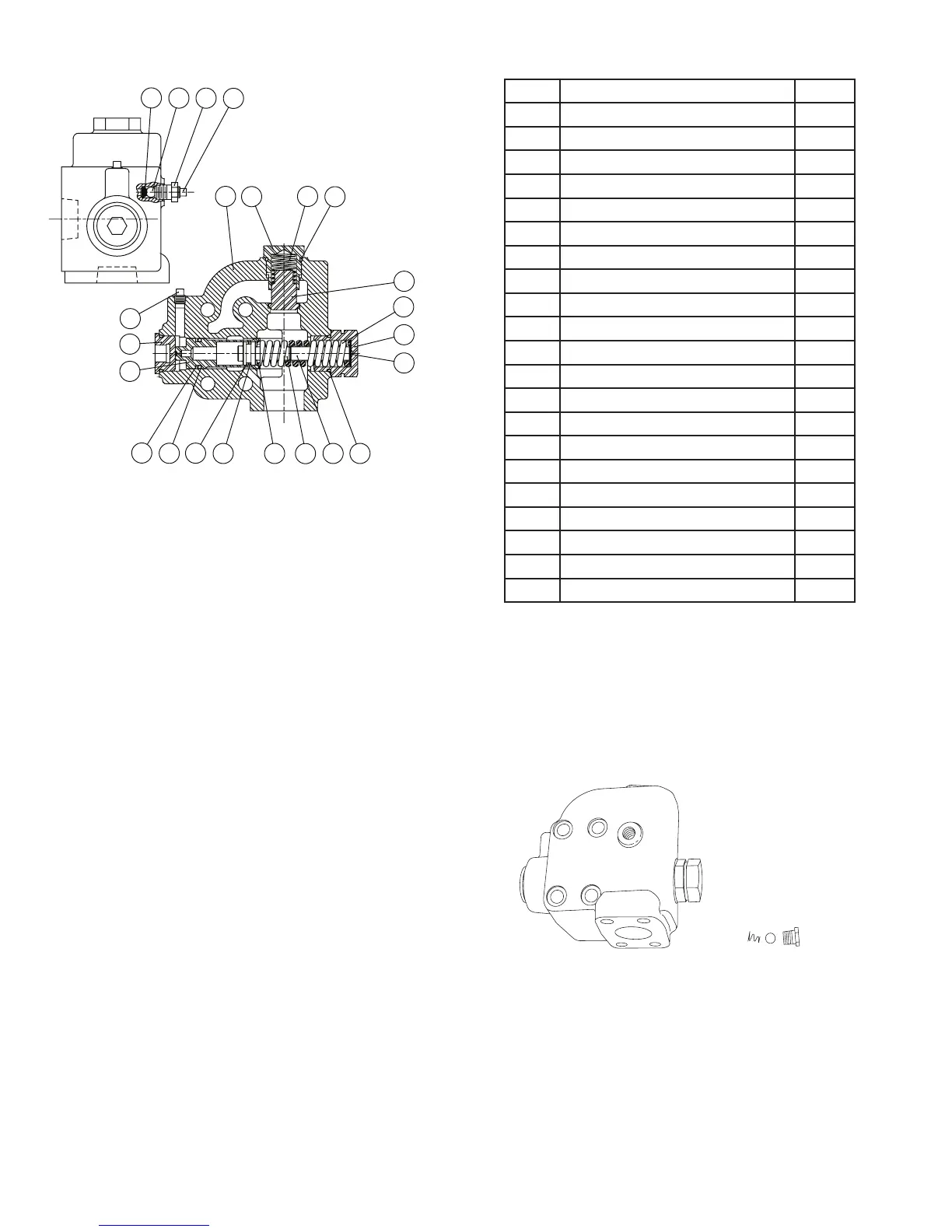
ITEM DESCRIPTION QTY.
1 Valve Housing 1
2 Check Valve Retainer 1
3 Spring Retainer 1
4 Plug 1
5 Main Piston 1
6 Damper Piston 1
7 Damper Piston Extension 1
8 Check Valve Poppet 1
10 Reducer 1
11 Check Ball 1
12 Check Valve Spring 1
13 Main Piston Spring 1
14 O-ring 1
15 Backup Ring 1
16 O-ring 1
17 Backup Ring 1
18 O-ring 1
19 Pipe Plug 1
20 Check Spring 1
21 Shim 1
22 Spring Seat 1
DISASSEMBLY
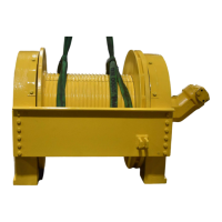
1. Remove the tting, motor drain check ball and
spring.