20 21
ENGLISH
Work steps for tting of adapter:
) Determine mounting base standard and size of fork and frame
(manufacturer).
) Determine the diameter of the rotor complying with the adapter.
) Make sure that the contact surface of the mounting base is milled
accurately and plain and is free of paint residues.
) Make sure that caliper seats plain and torsion-free on adapter or directly
on mounting base (PM).
Please skip the following 3 steps if you were able to determine that no
adapter is needed for the assembly of your disk brake (direct mounting).
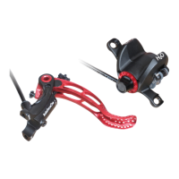
) Place adapter in the correct position on mounting base (pic. 2). Follow
direction arrow.
) Insert both screws by hand and turn them approx. 2–3 rotations.
) Set screws alternately until a tightening torque of 8 N·m (71 lbf·in) is
reached.
2.3 Fitting of Lever
⚠⚠
Loss of brake uid, air inclusion and damage of seals due to
caliper pistons moving off too far.
Don’t take out bleeding block out of caliper until wheels and rotors are tted.
Never pull lever when neither bleeding block nor rotors are between pads.
⚠⚠
Damage of hose.
Buckling, extreme bending or twisting of the hoses should be avoided at
all times.
It is possible that operating elements of shifters, suspension lockout or
seat post remote have to be moved for optimal ergonomics. Be sure to
check which combination will give you the best ergonomics possible.
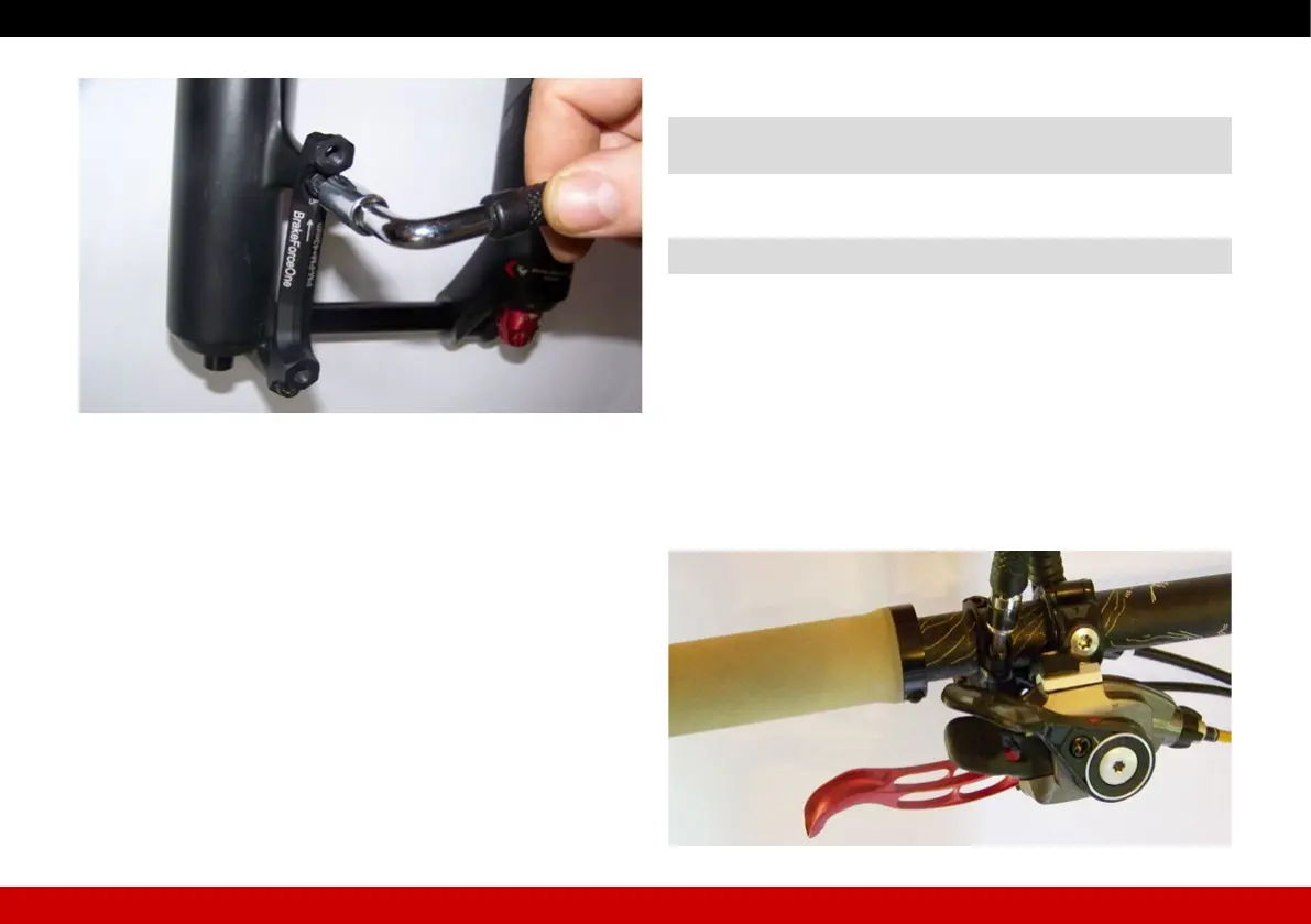
) When tting the lever make surre that lever can be reached easily with
your index nger when your hand is rested on the handle bar grip
(– see setting the lever, page 26).
) Set screws alternately until a tinghtening torque of 2 N·m (18 lbf·in) is
reached (pic. 3).
The gap of the clamp should be the same at top and bottom.
Picture 2
Picture 3
 Loading...