900IW Series Integrated Welders
Figure
Page
1-1
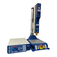
900IW+ Series Integrated Welder
1-3
2-1
Front Panel
2-1
2-2
Front Panel Displays
2-2
2-3
Back Panel
2-5
2-4
Right Side
2-6
2-5
Base
2-6
3-1
Overall Installation Dimensions
3-2
3-2
Base (Top View) Installation Dimensions
3-2
3-3
Hub Installation Dimensions
3-3
3-4
Transformer and Tap Locations
3-5
3-5
Remote Start Signals
3-6
3-6
Input/Output Signals
3-8
3-7
Operating Cycle Timing Table
3-9
3-8
Moving Jumpers
3-9
3-9
Hooking up an Air Line
3-10
3-10
Stud Torque Specifications
3-11
3-11
Assembling a Converter-Booster-Horn Stack
3-13
3-12
Assembling a Converter and Cylindrical Horn
3-13
3-13
Connecting Tip to Horn
3-14
3-14
Horn-Tip Torque Specifications
3-14
3-15
Installing the Stack
3-15
3-16
Adjusting the Mechanical Stop
3-18
3-17
DIP Switch Location
3-20
4-1
Parameter Functions
4-3
4-2
Limit Functions
4-4
4-3
Pretrigger Settings
4-6
4-4
Time Mode
4-7
4-5
Time Mode Parameters
4-8
4-6
Collapse Distance Mode
4-9
4-7
Collapse Distance Mode Parameters
4-9
4-8
Absolute Distance Mode
4-10
4-9
Absolute Distance Mode Parameters
4-11
4-10
Weld Parameter Values
4-13
4-11
Recalling Pre-defined Parameter Values
4-14
4-12
Manual Tuning Flow Chart
4-17
4-13
Setup and Operation in Time Mode
4-20
4-14
Setup and Operation in Collapse/Absolute Distance Modes
4-21
4-15
State Displays
4-22
4-16
Error Codes
4-25
List of Figures
 Loading...