I E16x442 Rev: 00 Page 32 of 73
5. Description of Monitor E1665
5.1. Display and Frontside Operational Elements
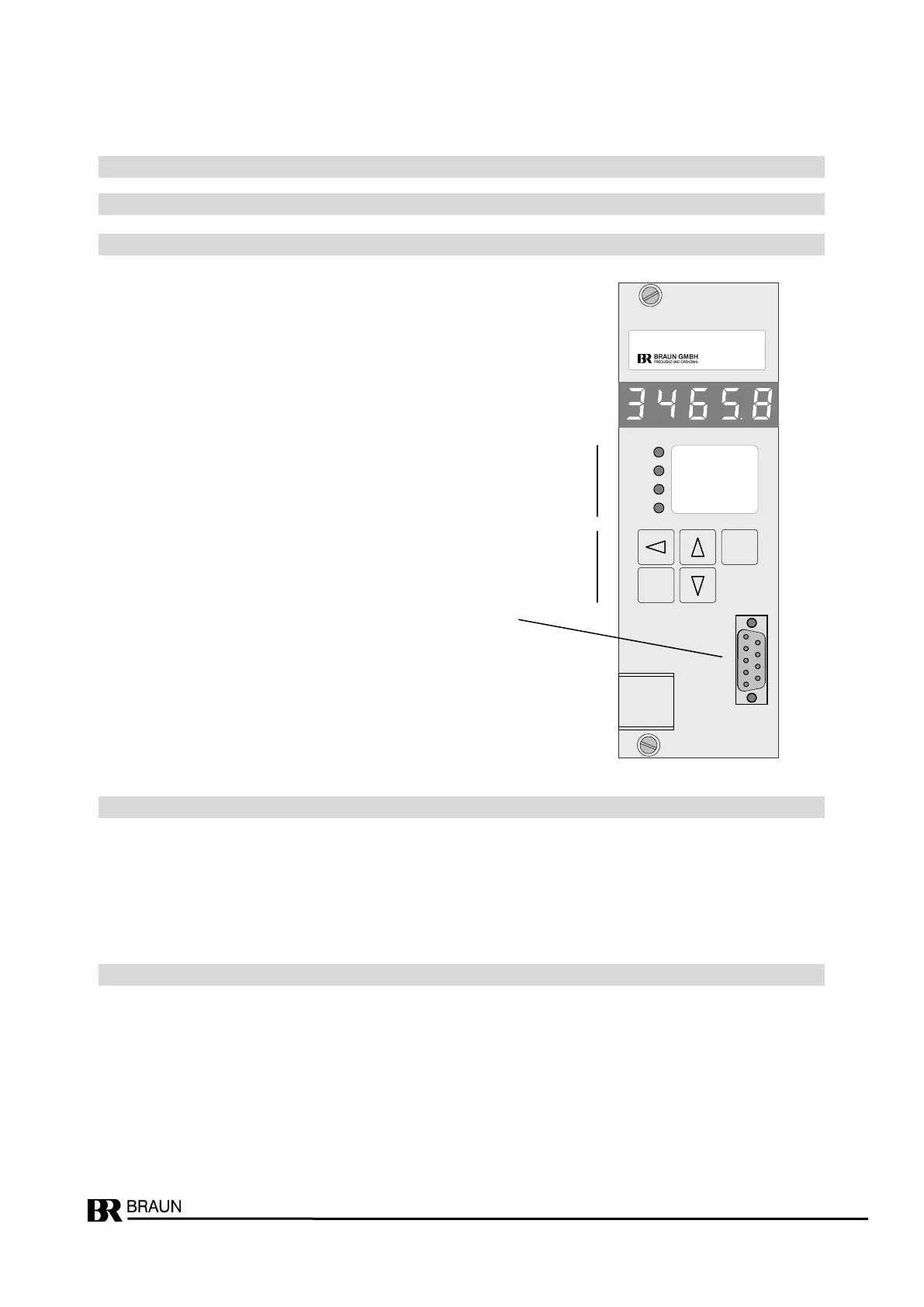
5.1.1. Front View of Monitor E1665
Figure 12: Front view of Monitor E1665
LED1 steady on: Trip
LED2 steady on: no Trip, SP1A is valid
blinking: SP1B is valid
LED3 steady on: n < SP3
blinking: one only of three input channels measures zero speed
LED4 steady on: n > SP3
5.1.3. Display during Test Procedures
FC-2 : External Trip-Release via Voter active
FC-3.1 : Trip-Line I is tested (Relay I to Trip-Condition)
FC-3.2 : Trip-Line II is tested (Relay II to Trip-Condition)
FC-3.4 : Trip-Line III is tested (Relay III to Trip-Condition)
SELF : Monitor self-test
4 LEDs for status indication
Data Interface
9-pole Sub-D