I E16x442 Rev: 00 Page 40 of 73
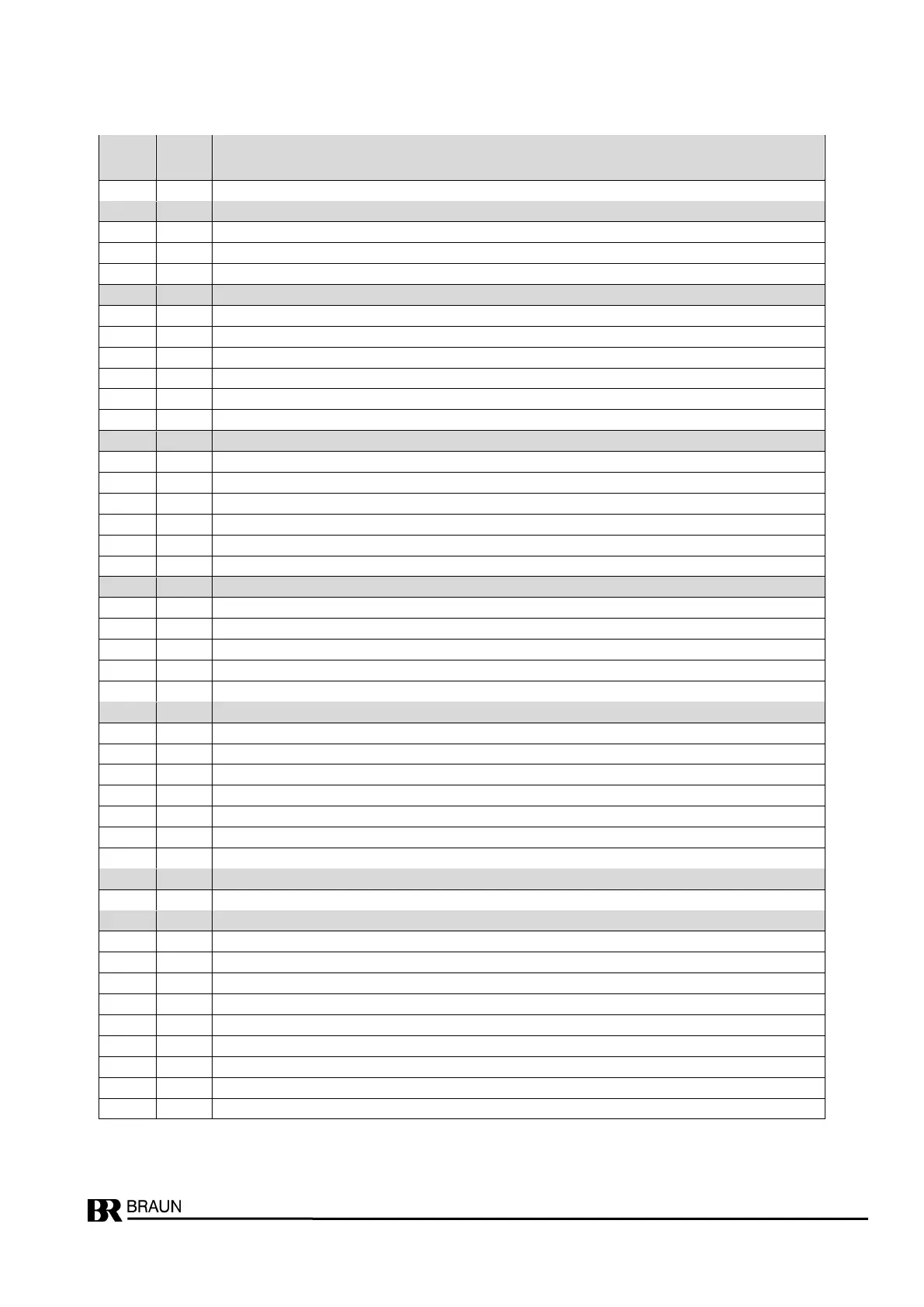
Hysteresis bandwidth (XX.X % of SP2)
Fix value = 0, do not change
Hysteresis bandwidth (XX.X % of SP3)
Hysteresis position: 0: above / 1: below
Relay state at "n > SP3" : 0 … 3 (see table)
Alarm state at sensor fault: 0: acc. to speed / 1: "n < SP" / 2: "n > SP"
Setting of LEDs to status "n > SP3" : 0: LED3 on / 1: LED4 on
Reserved for future application
Eddy sensor input check: input voltage upper limit in xx.x volts
input voltage lower limit in xx.x volts
current drain upper limit in xxx m
current drain lower limit in xxx m
Eddy sensor input hysteresis in x.x volts
Trip-Lines, Forward / Reverse Detection
Trip-Lines Monitoring: 0: no / 1: yes
Signal level Trip-Feedback: 0: low = Trip / 1: high = Trip
Forward / Reverse Detection Input level: 0: low = forward / 1: high = forward
Forward / Reverse relay state: 0: de-energized = forward / 1: energized = forward
Reserved for future application
Zero level: 0: dead zero / 1: live zero
Output level at sensor fault: 0: no change / 1: min / 2: max
Output direction: 0: 0/4 … 20 ma / 1: 20 ... 4/0 ma
Output response to test-speed: 0: test-speed / 1: frozen
Test of Analog Output value: 0: no / 1: yes
Reserved for future application
Reserved for future application
Operation Mode: 0 ... 5 (see table)
Input Truth Level: 0: high = Trip / 1: low = Trip
Voting logic: 0: 1oo2 / 1: 2oo2 / 2: 2oo3 / 3: 3oo3
Truth Time until Trip: 0 ... 11 (see table)
Trip latched: 0: no / 1: yes
Delay of Antivalence Alarm: 0 ... 9 (see table)


 To Next Page