Home
Bray
Controller
Series 70
Bray Series 70 User Manual
4
of 1
of 1 rating
32 pages
Give review
Manual
Specs
To Next Page
To Next Page
To Previous Page
To Previous Page
Loading...
29
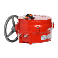
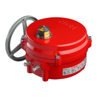
Series 70 Electric Actuator
Installation, Operation and Maintenance Manual
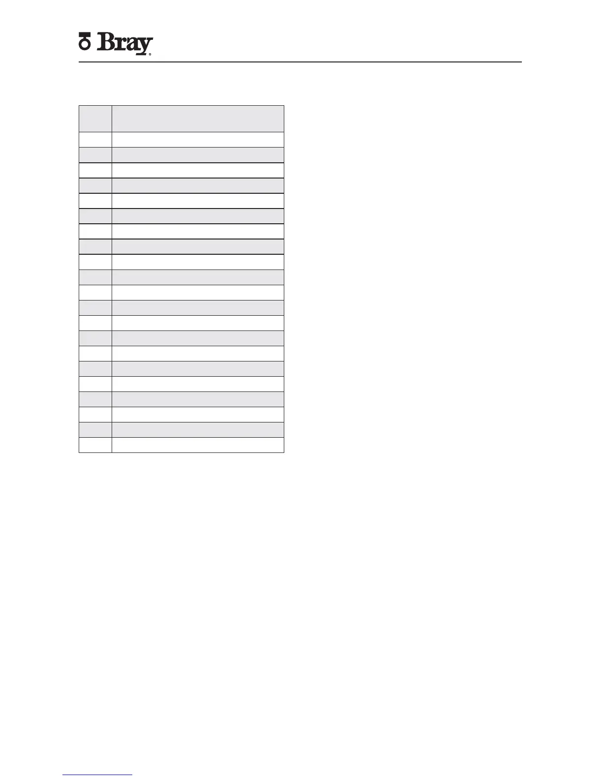
Item
No.
Description
1
Fastening Screw
2
Position Indicator Plate
3
Position Indicator Gasket
4
Actuator/Gear Box Gasket
5
Dowel Pin
6
O-Ring
7
W
asher
,Flat,Nylon
8
Nut,Hex
9
Bolt,Hex Hd
10
Cover
11
W
asher
, Conical
12
Actuator/Gear Box Fastening Screw
13
Output Gear Bearing
14
Idler/Input Gear Bearing
15
Cover Gasket
16
Input Gear
17
Output Gear
18
Idler Gear
19
Cover
20
Lock W
asher
21
Base Fastening Screw
30
32
Table of Contents
Table of Contents
3
Safety Instructions - Definition of Terms
4
Hazard-Free Use
4
Qualified Personnel
4
Part Numbering System Reference Chart
5
Introduction
5
Principle of Operation
5
Electrical Operation
5
Mechanical Operation
5
Actuation
6
Manual Operation
6
Remote Operation
6
S70 On/Off Actuator with Interposing Relay Board (I.R.B.)
6
Servo NXT
7
Storage
8
Commissioning
8
Mounting the Actuator
8
Wiring the Actuator
9
Setting Travel Limit Switches
9
Setting Mechanical Travel Stops
10
Disassembly and Assembly
12
Field or Factory Installable Options
15
Auxiliary Switches
15
Heater
15
Torque Switches
16
Local Control Station
16
Control Station Kit
16
Battery Backup Unit
17
Indication of Remote Control
18
Spinner
18
Receptacles (Quick Connectors)
18
External Signal Feedback Potentiometer
19
Basic Tools
20
Appendix A
20
Actuator Troubleshooting Chart
21
Appendix B
21
Series 70 - Size 003, 006 - Electric Actuator Exploded View
22
Series 70 - Size 008, 012, 020 - Electric Actuator Exploded View
24
Series 70 - Size 030, 050, 065 - Electric Actuator Exploded View
26
Series 70 - Size 130, 180 - Electric Actuator Exploded View
28
Series 70 - Size 130, 180 - 3:1 Gear Box Exploded View
30
Other manuals for Bray Series 70
Operation And Maintenance Manual
28 pages
4
Based on 1 rating
Ask a question
Give review
Questions and Answers:
Need help?
Do you have a question about the Bray Series 70 and is the answer not in the manual?
Ask a question
Bray Series 70 Specifications
General
Series
70
Accuracy
±1% of span
Repeatability
±0.5% of span
Housing Material
Aluminum
Input Signal
3-15 psi
Power Supply
N/A (Pneumatic)
Related product manuals
Bray 70 Series
48 pages
Bray SERVO PRO 70 Series
19 pages
Bray 92 Series
14 pages
 Loading...