8
Series 70 Servo Pro
Operation and Maintenance Manual
Switch
Command Input
4-20 mA DC 0-5 VDC 0-10 VDC 2-10 VDC
1 On Off Off Off
2 Off Off On On
3 Off Off Off On
10 Off On On On
Output
4-20 mA DC 0-5 VDC 0-10 VDC 2-10 VDC
4 On Off Off N/A
5 Off On On N/A
6 Off On On N/A
Forward
Acting
Reverse
Acting
7 Off On
Fail in
Last
Fail
Enable
8 Off On
Fail
Close
Fail
Open
9 Off On
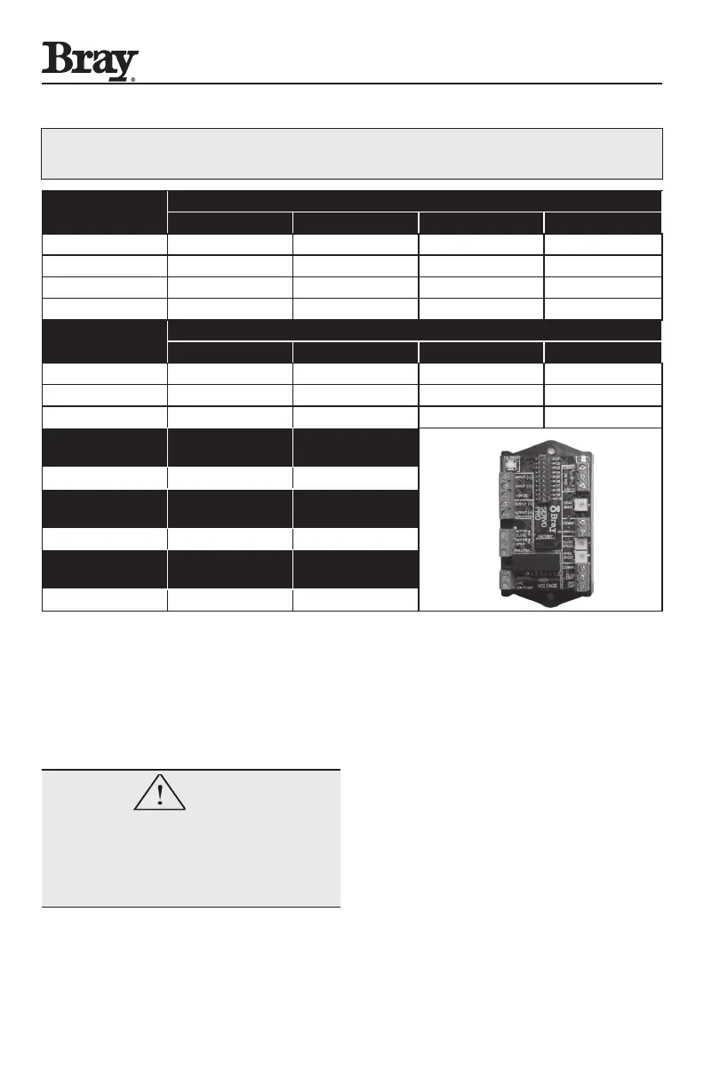
Table 2: Configuration Switch Chart for Servo Pro
Revision D
3.0 Quick Setup Instructions
WARNING
Do not connect the electric power supply until
instructed to do so.
Refer to the Configuration Switch charts and
descriptions in Sections 2.1, 2.2 and 2.3 when
performing the Quick Setup.
A. Set the Command Signal Input configuration.
B. Set the Feedback Output Signal configuration.
C. Select the Operating Mode (Forward Acting or
Reverse Acting)
D. Select Fail Enable or Fail in Last Position
a. If Fail Enable is selected, then select Fail Open
or Fail Close with Switch 9
b. If Fail Enable is not selected, the actuator will
Fail in Last Position
E. Verify (or adjust) the travel stop limits in the
actuator
a. Bray actuators are shipped with the travel
switches in the factory default position - close
travel limit set at 0 degrees and the open travel
limit set at 90 degrees
b. Bray actuators equipped with Servo Pro have
the internal feedback potentiometer set in the
NOTE: The following chart is for configuration of an older model Servo Pro (Rev. D).
Please verify that the model you are using is the same model before consulting this chart.

 Loading...

