5
Series 70 Servo Pro
Operation and Maintenance Manual
2.2 Configuration Switches
NOTICE
Disconnect all electric power to the Servo Pro prior to adjusting configuration switches. Reconnect
electric power only after all the configuration switches are in the proper position.
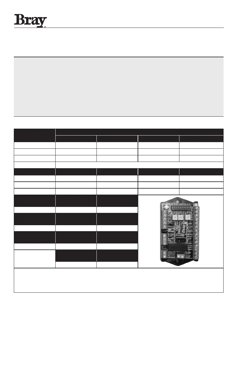
The configuration switches are located on the top edge of the Servo Pro Revision F or higher,
between the Calibration button and the Status LED.
Carefully observe the ON and OFF orientation for each section of the configuration switches when
selecting desired options
Table 1: Configuration Switch Chart for Servo Pro
Revision F or Higher
Switch
Command Signal Input
4-20 mA DC 0-5 VDC * 0-10 VDC 2-10 VDC
1 Off On On On
2 Off Off On On
3 Off Off Off On
Feedback Output Signal
4-20 mA DC 0-5 VDC 0-10 VDC 2-10 VDC
4 Off On On N/A
5 On Off Off N/A
6 Off On Off N/A
Forward
Acting
Reverse
Acting
7 Off On
Fail in
Last Position
Fail
Enable **
8 Off On
Fail
Close
Fail
Open
9 Off On
10
Torque
Switch Enable
Torque
Switch Disable
Off On
*To control the Servo Pro with a remote potentiometer, set the Command Input to 0-5VDC
(see Command Signal Notice section; page 8).
**Fail position is the position that the Servo Pro will move the actuator when the control signal is
removed. It does not apply to 0-5VDC or 0-10VDC Command Signals.

 Loading...

