16
Series 70 Servo Pro
Operation and Maintenance Manual
NOTICE
A torque switch that is broken, improperly wired,
or missing from the actuator can result in an open
contact which will be interpreted by the Servo Pro
as the actuator being at its max torque limit.
If the optional torque switches are not installed,
select Torque Switch Disable by setting
Configuration switch 10 to ON.
CAUTION
Do not connect any high voltage power to the
torque limit switch terminals as damage could
result.
5.1.7 Feedback Potentiometer
The Servo Pro uses the signal from the internal
feedback potentiometer to determine the current
actuator position.
The wiring to the feedback potentiometer is
connected at the factory and should not require
any adjustment by the customer. If a field repair is
required, follow the instructions below:
5.1.7.1 Feedback Potentiometer Instal-
lation and Calibration
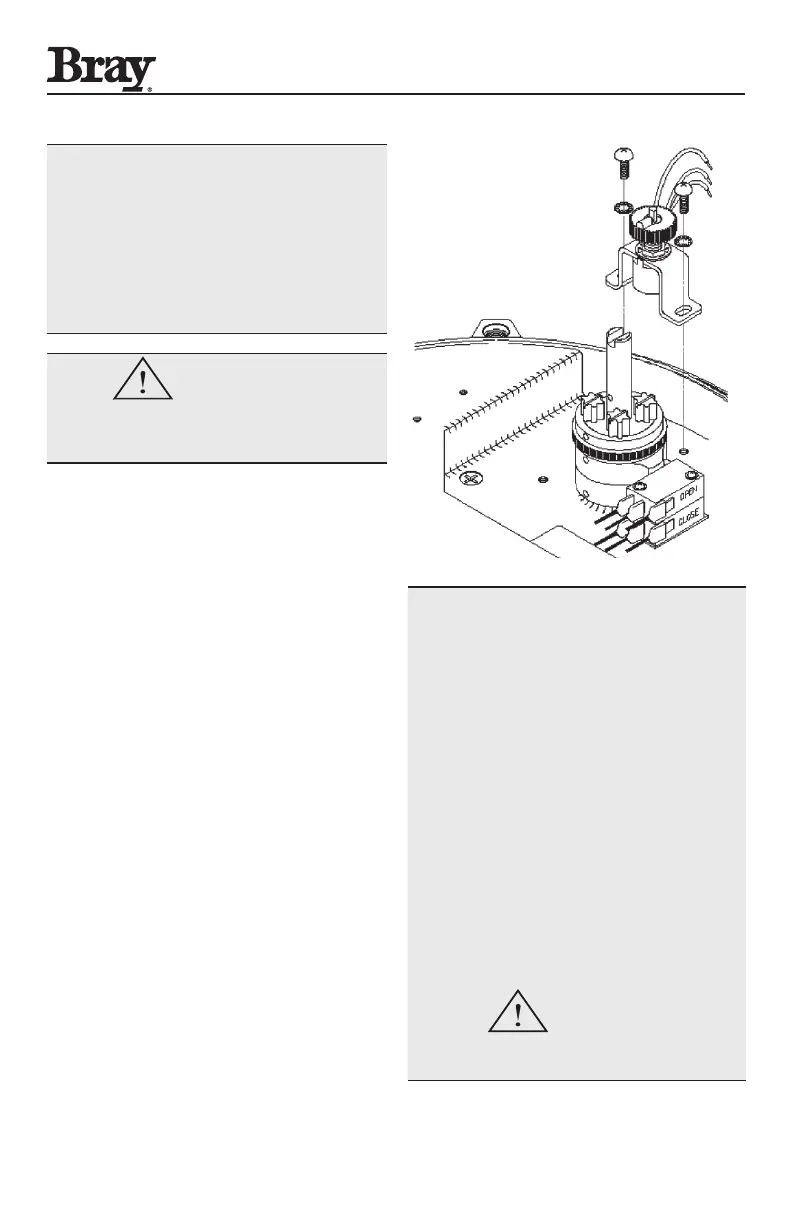
1. Install the internal feedback potentiometer next
to the actuator indicator shaft using the two
threaded mounting holes provided.
2. The potentiometer assembly must be mounted
in the correct orientation in order to successfully
calibrate the Servo Pro.
3. Remove the indicator rotor from the indicator
shaft so that the drive slot on the top is visible.
4. Engage the handwheel (pulling it fully outward)
and manually move the actuator to the fully open
(counterclockwise) position.
5. Use the black feedback pot knob to rotate the
black feedback pot cam until the raised green rib
on the pot gear (see Figure 4 below) is directly in-
line with the slot on the top of the indicator shaft.
6. The actuator is now ready for the calibration
procedure described in Section 3.1.
NOTICE
The wiring of the feedback pot is critical to proper
operation.
Connect the orange wire from the wiper pin of the
pot to the middle terminal.
Connect the gray wire from the fixed pin of the
pot that is closest to the wiper pin to the +5V
terminal.
Connect the white wire from the fixed pin of the
pot that is farthest from the wiper pin to the COM
terminal.
Connect a voltmeter between the middle terminal
and the COMMON terminal. Apply power to the
Servo Pro, move the actuator to the fully open
position, and the reading should be close to
+5 VDC. Move the actuator to the fully closed
position, and the reading should be close to 0 VDC.
CAUTION
Do not connect any high voltage power to the
feedback pot terminals as damage could result.
Figure 4: Feedback Pot Mounting and Positioning.

 Loading...

