12
Series 70 Servo Pro
Operation and Maintenance Manual
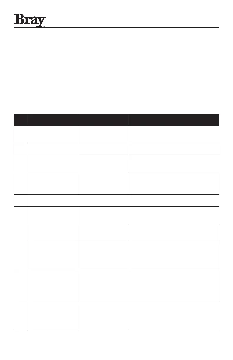
4.4 Status LED Flash Codes
Table 3 shows various diagnostic Flash Codes and
their descriptions.
If more than one advisory condition or error
condition exists, only one Flash Code will appear at
a time. The first condition must be corrected before
the second (or subsequent) Flash Code will appear.
Table 3: Status LED Flash Codes
No. Indication Description Possible Solution(s)
1
Steady Green Flash
(1 second on, 1 second
off) “Heartbeat”
Normal Operation Servo Pro Functioning Normally
2
2 Green Flashes
Calibration Defaults
Loaded
Calibration may be acceptable, but if not,
adjust travel limits and restart the Calibration
3
3 Green Flashes
Reverse Acting Mode
Selected
This is an advisory that the Reverse Acting
mode has been selected. Adjust Configuration
switch 7 if forward operation is required.
4
4 Green Flashes
HVAC 2-10 VDC
Command Signal
Selected
This is an advisory that the HVAC 2-10 VDC
input has been selected. Adjust Configuration
switches 1, 2 and 3 if this Command Signal is
not required.
5
1 Red Flash Handwheel engaged
Push the Handwheel in towards the actuator
to Disengage
6
2 Red Flashes Command Signal Failure
Verify Command Signal, verify wiring, adjust
Configuration switches to match Command
Signal
7
3 Red Flashes Feedback Pot Fault
Verify feedback pot wiring, position the
feedback Pot cam correctly, see Feedback Pot
calibration notes
8
4 Red Flashes Limit Switch Fault
Verify wiring of limit switches, verify limit
switch cam settings, verify that both limit
switches are not tripped simultaneously (the
actuator cannot be fully open and fully closed
at the same time)
9
5 Red Flashes Torque Switch Fault
Verify that optional torque switches are
installed and wired correctly, reverse
direction of actuator, correct over-torque
condition – OR – if optional torque switches
are not installed, disable the torque switch
input setting Configuration switch 10 to ON.
10
6 Red Flashes
Feedback Pot Wired In
Reverse
This check is only performed during
Calibration. Remove power from the Servo
Pro, correct the wiring to the feedback pot,
reapply power to the Servo Pro, and restart
the Calibration.

 Loading...

