5
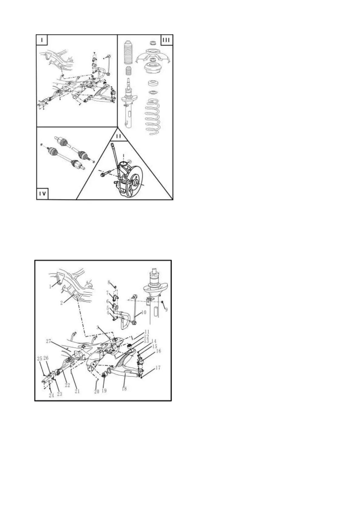
Front axle - schematic drawing
I Dismantle front suspension beam assembly,
stabilizer bar and rocker arm assembly →
page 4
II Repair wheel bearing → page 12
III Repair shock absorber → page 19
IV Repair transmission shaft → page 24
Section 1 Front suspension beam assembly, stabilizer
bar and rocker arm assembly
I – Schematic drawings for assembling front
suspension beam assembly, stabilizer bar
and rocker arm assembly
Description:
◆ If vehicle has to be moved after transmission
shaft is dismantled, first assemble the external
constant velocity cardan joint and fasten it with
torque of 50Nm, otherwise wheel bearing may
be damaged.
Do not perform welding and correction on load
bearing part or wheel alignment part.
◆ Replace locknut
◆ Replace rusted nut/bolt
1- Bracket of front suspension beam assembly
2 - Weld nut on body
◆ If weld nut thread on beam is damaged, use
tapping tool to re-tap it
3 - Prevailing torque type hexagon nuts with flange
(with non-metallic insert) M12×1.25
◆ Replace it after each diamantling