ACS5000 Installation Manual Page 22
© 2017 Brivo Systems LLC. All rights reserved. Rev 1
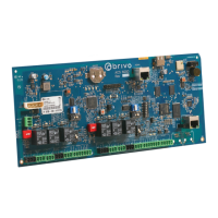
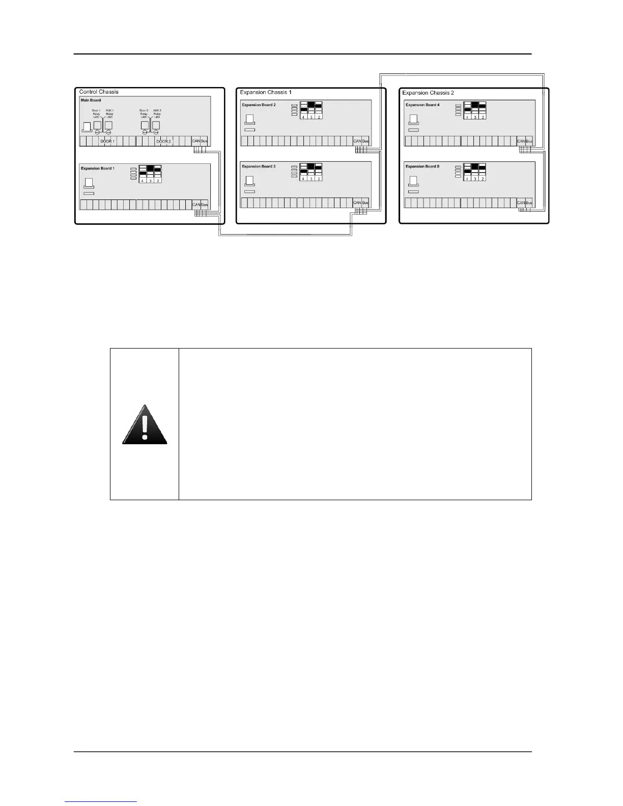
Figure 11. CAN BUS Configuration
4. Use standard CAT5 or CAT6 (unshielded twisted pair) cabling to connect all the boards in the
control panel via the CAN BUS terminals.
5. Always connect like terminals to one another (i.e., A to A, B to B, and so on.).
6. Follow the color coding shown on the wiring diagram on the inside of the chassis door.
WARNING: CAN BUS Wiring
THE A/B CIRCUITS MUST SHARE A TWISTED PAIR, AND THE C/D CIRCUITS
MUST SHARE A TWISTED PAIR. Otherwise, the distance and data integrity of the
communications channel will be compromised.
WHEN USING JUST A MAIN BOARD, THE JUMPER MUST REMAIN ATTACHED TO
THE CAN TERM HEADER ON THE MAIN BOARD. If expansion boards are used,
this jumper remains attached on the very last board(s) in the daisy chain; i.e. It
must be removed from all boards except the endpoint of the daisy chain.
(NOTE: The MAIN BOARD does not have to be an endpoint in the control panel;
the control panel may be in the middle of the chain with expansion boards
branching out in either direction.)
7. On the first board, connect the wires of the CAT5/CAT6 cable to the CAN BUS terminal block
as follows:
a) Connect the green wire to the A terminal.
b) Connect the green and white wire to the B terminal.
c) Connect the blue wire to the G (ground) terminal.
d) Connect the orange wire to the C terminal.
e) Connect the orange and white wire to the D terminal.
8. After all the wires of the CAT5/CAT6 cable are connected to the first board, connect the wires
to the second board in the same manner.
9. Connect the CAN NODE ADDRESS jumpers. The silkscreen next to the CAN NODE ADDRESS
pins shows how to position the jumpers for first four addresses.
10. Positions for additional address values are shown in the diagram below.
 Loading...