ACS5000 Installation Manual Page 7
© 2017 Brivo Systems LLC. All rights reserved. Rev 1
Verify that the client site is ready to support the installation.
1. Check with the IT department to ensure that the ACS5000 to be installed is compatible with
the company’s local area network (LAN).
a) The ACS5000 is equipped with a standard RJ-45 socket that accepts a CAT5 cable
with an RJ-45 plug on any 10/100 Ethernet network. Physically connecting the panel
is the same as plugging any computer or other device into the LAN.
b) Refer to the Panel Networking Admin Interface Guide (or the Brivo OnSite
Administrator’s Manual in the case of the ACS5000-S) for instructions on connecting
to the LAN. The Panel Networking Admin Interface Guide (or Brivo OnSite
Administrator’s Manual) also contains a complete list of requirements regarding
TCP/IP configuration parameters, firewall and proxy settings, and information about
security considerations.
2. Download the appropriate Quick Start Guide from the Brivo website and provide it to the
Master Administrator. This document provides instructions for registering and configuring the
control panel in the appropriate application.
3. For Brivo OnAir accounts, make sure the account has been created and the control panel is
registered through Brivo OnAir. If the control panel has not been registered by the dealer, the
installer may either contact Brivo Technical Support for assistance or simply register the panel
directly.
4. Verify that the Master Administrator and any other employee who will be accessing the system
have Internet access on a computer equipped with a supported Web browser.
Verify shipping contents.
1. Locate and check the contents of the Control Panel kit.
The ACS5000 kit should contain the following parts:
a) 1 metal chassis (MCH-CHA-0001). Packed inside the chassis are:
• An identify label (ENG-LBL-0001) to be adhered to the inside of the door.
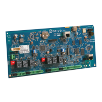
• 1 cardboard box containing the MAIN BOARD (B-ACS5000) (#1181-01-
0101A) and an Identity Label (#ENG-LBL-0004).
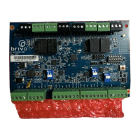
• 1 cardboard box containing a power supply board (#1181-01-0104A).
• 1 cardboard box containing accessories, including:
o 1 AC transformer (#ELC-XFM-AMS1)
o 1 7 Ah lead-acid battery (#ELC-BAT-B7001)
o 1 power cable assembly (#ELC-PWR-A001)
o 2 MOVs (Metal Oxide Varistors), (#ELC-MOV-M001)
o 16 EOL (End of Line) resistors (#ELC-EOL-R001)
o 2 10-inch 18-gauge battery wires (1 red, 1 black), with female
spade-type connectors (#ELC-BAT-W001)
o 1 AC Power Indicator LED (ELC-LED-L001).
b) 1 lock and key set (#MCH-LCK-0001)
c) 5 screws for power supply (#MCH-SCW-0001)
d) 5 standoffs for the MAIN BOARD (#MCH-SFF-0001)