ACS5000 Installation Manual Page 8
© 2017 Brivo Systems LLC. All rights reserved. Rev 1
e) 1 tamper switch assembly (#ELC-TMP-A001)
f) 1 documentation set, including:
• Installation Manual (this document)
5. If additional DOOR BOARDs have been ordered with the control panel, locate and check the
contents of each 2-Door Board Kit (B-ACS5000-DB). There may be up to 14 of these kits (for a
total of 15 including the MAIN BOARD) and each should contain the following parts:
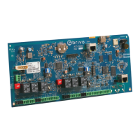
a) 1 DOOR BOARD (#1181-01-0102A).
b) 5 standoffs for the DOOR BOARD (#MCH-SFF-0001)
c) 6 EOL resistors (#ELC-EOL-R001)
d) 2 MOVs (Metal Oxide Varistors) (#ELC-MOV-M001)
e) 1 power cable assembly (#ELC-PWR-A001)
6. If additional INPUT OUTPUT BOARDs have been ordered with the control panel, locate and
check the contents of each INPUT OUTPUT BOARD Kit (B-ACS5000-IO).There may be up to 14
of these kits (for a total of 15 including the MAIN BOARD), and each should contain the
following parts.
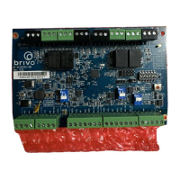
a) 1 INPUT OUTPUT BOARD (#1181-01-0103A).
b) 5 standoffs for the INPUT OUTPUT BOARD (#MCH-SFF-0001)
c) 8 EOL resistors (#ELC-EOL-R001)
d) 1 power cable assembly (#ELC-PWR-A001)
7. If additional expansion chassis have been ordered with the control panel, locate and check
the contents of each Expansion Chassis Kit (B-ACS5000-EXP) or Large Expansion Chassis Kit
(B-ACS5008-EXP). Each standard expansion chassis can hold up to two boards, including any
combination of door and/or Input Output boards. Each large expansion chassis can hold up to
four boards, including any combination of door and/or Input Output boards. There may be
enough Expansion Chassis kits or Large Expansion Chassis Kits to hold 1 MAIN BOARD, and
any combination of 14 door and/or Input Output boards. Each should contain the following
parts:
a) 1 metal chassis (MCH-CHA-0001)
b) 1 lock and key set (#MCH-LCK-0001)
c) 5 screws for power supply (#MCH-SCW-0001)
d) 1 door label showing wiring and setup guide (Inside Door Label – Expansion (#ENG-
LBL-0003)
e) 1 tamper switch assembly (#ELC-TMP-A001), containing a tamper switch (ELC-TMP-
S001), wire (ELC-TMP-W001, and header connector (ELC-TMP-HC01)
f) 1 power supply board (#1181-01-0104A).
g) 1 AC transformer (#ELC-XFM-AMS1)
h) 1 pair of battery wires (#ELC-BAT-W001)
i) 1 AC Power Indicator LED (ELC-LED-L001), pre-installed in the chassis door.
j) 1 7 Ah lead-acid battery (#ELC-BAT-B7001)
Plan your installation.
1. Determine the size of your control panel.