ACS5000 Installation Manual Page 28
© 2017 Brivo Systems LLC. All rights reserved. Rev 1
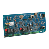
1. An INPUT OUTPUT BOARD has 8 output relays and 8 inputs. The inputs can be wired for line
supervision.
2. The ACS5000 is capable of 4-state input monitoring at each input connector, whether it be on
the Main Boar
3. d, a Door Board, or an Input Output Board. This allows for monitoring of not only open and
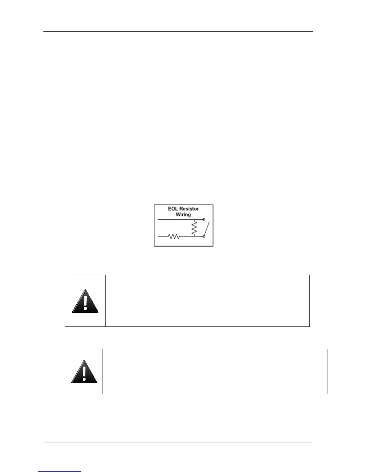
closed switches, but cut and short-circuited lines as well. This can only happen when the EOL
(end-of-line) resistor wiring is installed.
a) You will need two 2Kohm resistors for each input.
b) The resistors are installed on the input lines as close to the switch as possible, and
as far from the ACS5000 control panel.
c) One resistor is placed in parallel with the switch, so that one end of the resistor is
connected to wire 1 from the switch, while the other end is connected to wire 2 from
the switch.
d) The second resistor is placed in series with the switch, so that one end of the resistor
is connected to wire 1 from the switch, while the other end is connected to the wire
leading to the ACS5000 control board.
e) The other wire from the ACS5000 is connected to wire 2 from the switch, as shown in
Figure 18.
Figure 18. EOL Resistor Wiring
WARNING: Powering Electronic Strikes and Latches
DO NOT POWER ELECTRONIC STRIKES AND LATCHES WITH THE BATTERY
(OR OTHER POWER SOURCE) USED TO POWER THE CONTROL PANEL; DOING
SO WILL CAUSE DAMAGE TO THE BRIVO CONTROL PANEL. USE ONLY A UL
LISTED BURGLAR ALARM OR ACCESS CONTROL SYSTEM TO POWER
ELECTRONIC STRIKES AND LATCHES.
WARNING: Grounding the control chassis
Grounding the chassis is an important final step in the installation process and
should not be ignored. If the chassis is not (or is improperly) grounded, this may
cause issues with the electronics of the panel and may have implications involving
warranty return of equipment.
 Loading...