38
GENLOCK OK LED
This LED will light when a valid genlock video signal is connected to the MicroSYNC genlock video input.
REFERENCE VIDEO INPUT
These two BNC connectors provide a loop-through (bridging) connection for the genlock reference input. Composite
color black or another stable composite video signal such as color bars should be used as a genlock reference. The
signal loop should always be terminated in 75O. If the MicroSYNC card represents the end of the reference loop, a
precision 75O BNC terminating plug should be installed on the unused jack.
When stand-alone operation is desired, the MicroSYNCs genlock external/internal option should be set to internal. This
option can be set via software or from the front panel of an ES-2200 series expansion chassis.
GENLOCK TIMING ADJUSTMENT
The rear panel genlock timing adjustment can only be used when the MicroSYNC remote control capability is disabled
(DIP Switch 8 DOWN). Do not adjust this switch if you are operating the MicroSYNC by the RC-2000 control panel.
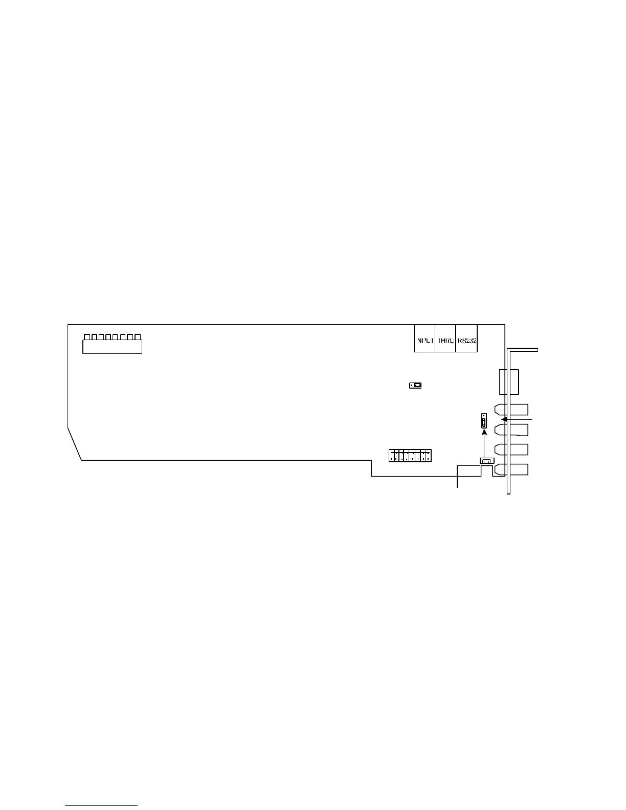
8 7 6 5 4 3 2 1
INTERNAL SERIAL DATA
CONNECTORS
MUTE
TRANSMIT
BSW1
DIP Switches
DHE5
CHE2
BNC
BUS
CHE3
BUS Input
MicroSYNC Video
BUS Output
Serial Data
Transmit Control
Note:
Do not install jumper CHE3 unless is being fed by a single
RS-2800 Routing Switcher.
Figure 4-6: DPS 8-Bit MicroSYNC Card