Broadcom 95xx User Guide
Broadcom
®
95xx PCIe 4.0 MegaRAID
®
and HBA Tri-Mode Storage Adapters
Cables and Cabling Configurations
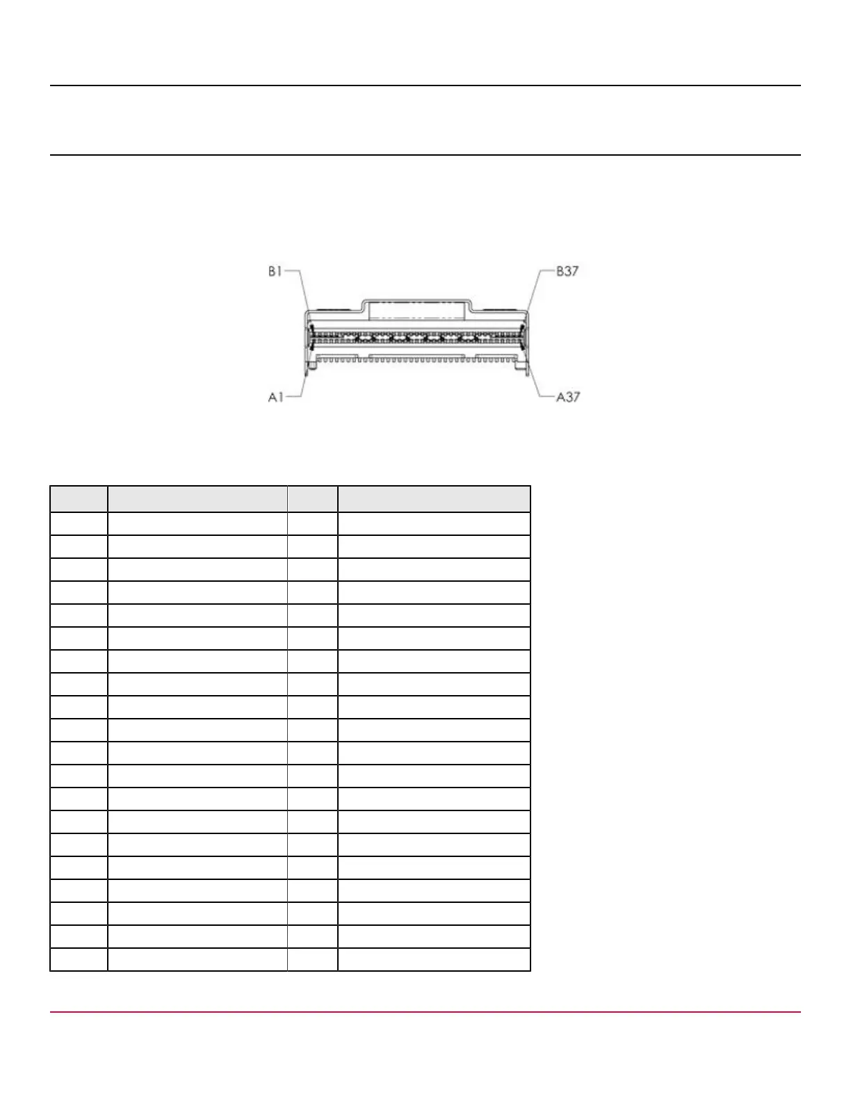
The internal adapter follows the SFF-9402 standard for connector signal assignments. Each x8 connector includes eight
PCIe transmit and receive lanes and two sets of sidebands designated as A and B, in accordance with the SFF-9402
specification. The following figure shows the x8 SFF-8654 pin designations.
Figure 1: x8 SFF-8654 Pin Designations
The following table defines the adapter’s internal x8 SFF-8654 connector pinouts.
Table 8: Internal x8 SFF-8654 Connector Pinout
Pin Name Pin Name
A1 GND B1 GND
A2 PERp0, RX0+ B2 PETp0, TX0+
A3 PERn0, RX0- B3 PETn0, TX0-
A4 GND B4 GND
A5 PERp1, RX1+ B5 PETp1, TX1+
A6 PERn1, RX1- B6 PETn1, TX1-
A7 GND B7 GND
A8 BP_TYPEA B8 2W-CLKA, SClockA
A9 2W_RESETA,SDataOutA B9 2W-DATAA, SloadA
A10 GND B10 GND
A11 REFCLKA+ B11 PERSTA#, SDatainA
A12 REFCLKA- B12 CPRSNTA#, CNTRLR_TYPEA
A13 GND B13 GND
A14 PERp2, RX2+ B14 PETp2, TX2+
A15 PERn2, RX2- B15 PETn2, TX2-
A16 GND B16 GND
A17 PERp3, RX3+ B17 PETp3, TX3+
A18 PERn3, RX3- B18 PETn3, TX3-
A19 GND B19 GND
A20 PERp0, RX4+ B20 PETp0, TX4+
Broadcom
95xx-MR-HBA-Tri-Mode-UG104
16