Broadcom 95xx User Guide
Broadcom
®
95xx PCIe 4.0 MegaRAID
®
and HBA Tri-Mode Storage Adapters
Broadcom MegaRAID and HBA Tri-Mode Storage Adapter
Characteristics
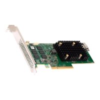
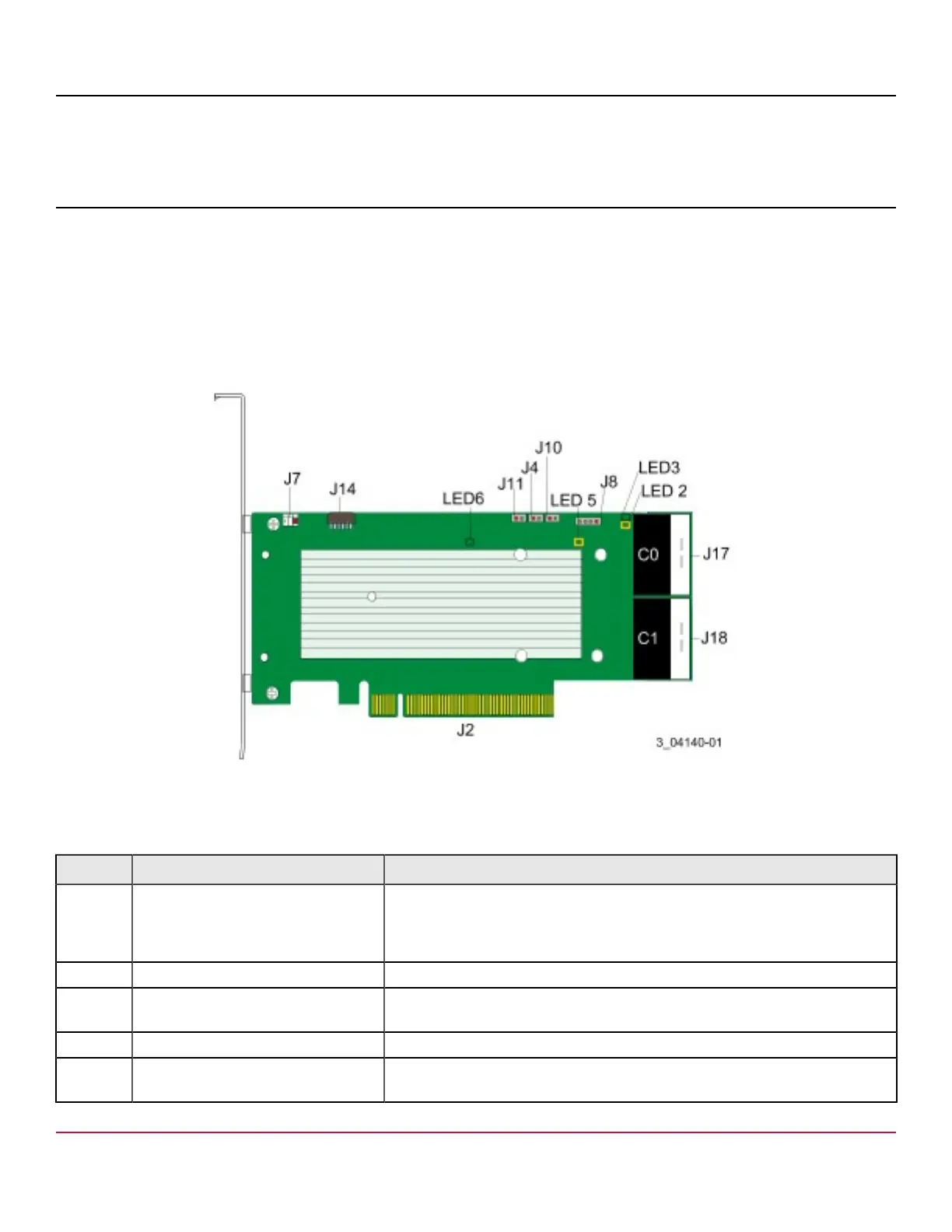
MegaRAID 9560-16i Adapter – Connector and LED Designations
The adapter is a 6.127 in. × 2.712 in. (155.65 mm × 68.90 mm) board. The component height on the top and bottom of the
adapter complies with the PCIe specification.
The following figure shows the connectors and LED locations on the adapter. Pin 1 on the headers and connectors is
highlighted in red in the figure.
Figure 3: Card Layout for the MegaRAID 9560-16i Tri-Mode Storage Adapter
The following table describes the headers and connectors on the adapter.
Table 12: Headers and Connectors
Connector Type Description
J2 Standard edge card connector The interface between the storage adapter and the host system.
With the PCIe interface, this connector provides power to the board and an
I
2
C interface connected to the I
2
C bus for the Intelligent Platform Management
Interface (IPMI).
J4 Default serial boot ROM (SBR) header 2-pin connector. Reserved for Broadcom use.
J7 Advanced software options hardware
key header
2-pin connector.
Enables support for selected advanced features.
J8 Onboard serial UART connector 4-pin connector. Reserved for Broadcom use.
J10 Global HDD activity LED header 2-pin connector.
Connects to an LED that indicates activity on the drives connected to the adapter.
Broadcom
95xx-MR-HBA-Tri-Mode-UG104
24