Broadcom 95xx User Guide
Broadcom
®
95xx PCIe 4.0 MegaRAID
®
and HBA Tri-Mode Storage Adapters
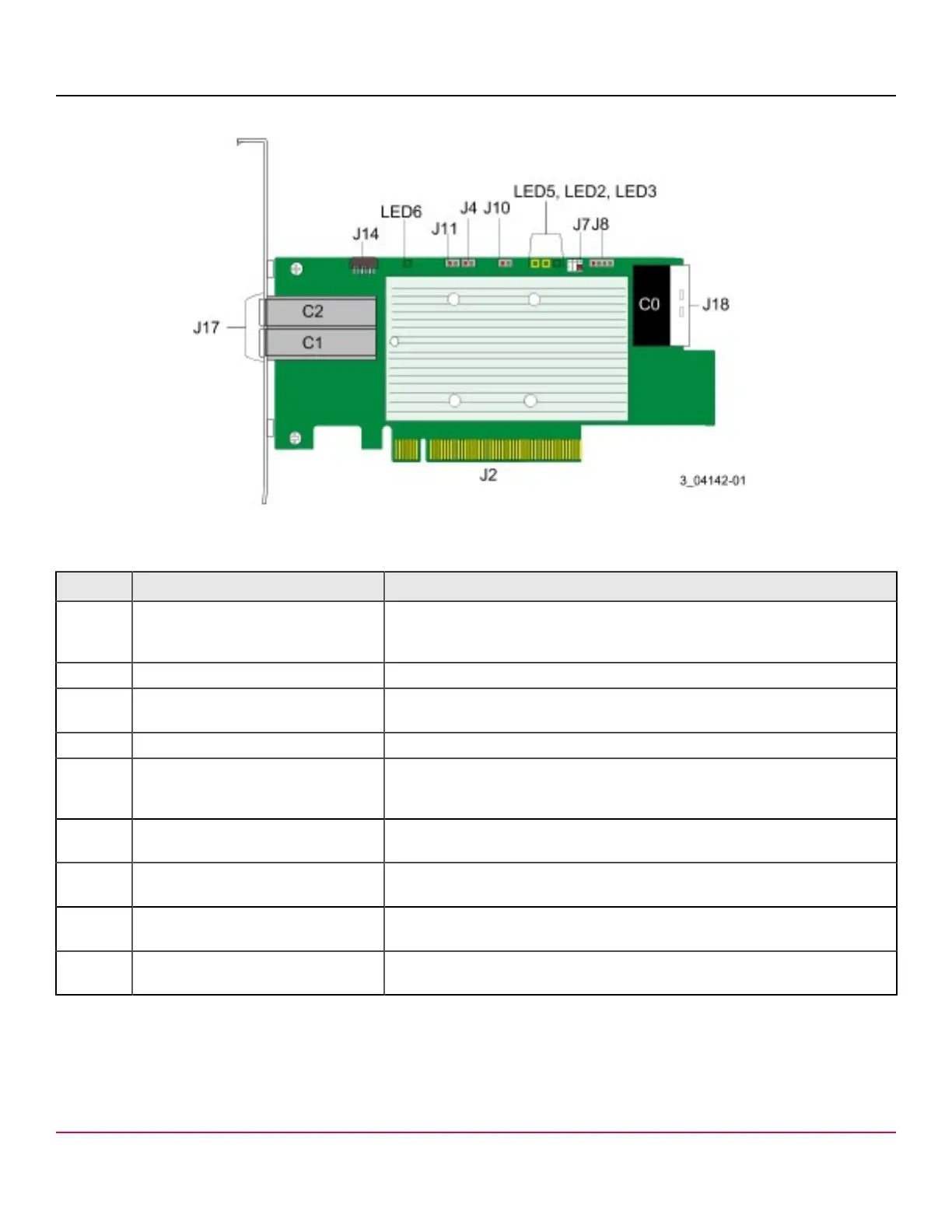
Figure 5: Card Layout for the MegaRAID 9580-8i8e Tri-Mode Storage Adapter
Table 16: Headers and Connectors
Connector Type Description
J2 Standard edge card connector The interface between the storage adapter and the host system.
With the PCIe interface, this connector provides power to the board and an I
2
C
interface connected to the I
2
C bus for the IPMI.
J4 Default SBR header 2-pin connector. Reserved for Broadcom use.
J7 Advanced software options hardware
key header
2-pin connector.
Enables support for selected advanced features.
J8 Onboard serial UART connector 4-pin connector. Reserved for Broadcom use.
J10 Global HDD activity LED header 2-pin connector.
Connects to an LED that indicates activity on the drives connected to
the controller.
J11 Global drive fault LED header 2-pin connector.
Connects to an LED that indicates whether a drive is in a fault condition.
J14 CacheVault power module interface 9-pin connector.
Connects the adapter to a CacheVault power module.
J17 Storage interface connector Two SFF-8644 4-port external connector.
Connects the adapter by cable to the storage devices.
J18 Storage interface connector One SFF-8654 8-port internal connector.
Connects the adapter by cable to the storage devices.
The following table describes the LEDs on the adapter.
Broadcom
95xx-MR-HBA-Tri-Mode-UG104
27