52 Brocade FastIron GS and FastIron GS-STK Hardware Installation Guide
53-1001783-01
Upgrading hardware
4
DRAFT: BROCADE CONFIDENTIAL
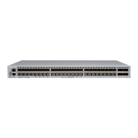
FIGURE 43 Remove cover plate from 10 Gbps module slot
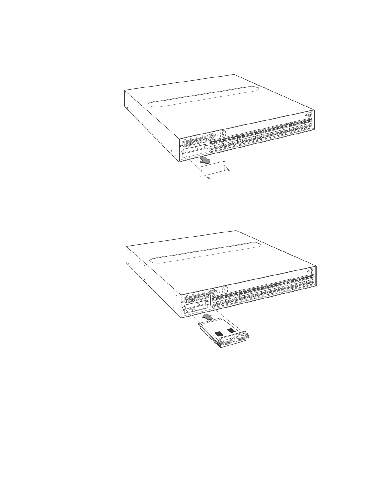
13. Insert the CX4 module into the slot, push gently to engage the connectors, and tighten the
thumbscrews on the module faceplate, as shown in Figure 44.
FIGURE 44 Install the CX4 Module
14. Replace the cover as follows:
• Hold the cover on each side at the center and align the front of the cover with the end of
the serial interface on the front panel, so that the cover extends slightly past the front
panel of the device.
• Slide the cover backwards until it is fully flush with the top of the device.
• Re-insert the cover screws.
15. If applicable, re-attach the rack mounting ears.
16. Reinstall the device in an equipment rack, if necessary.
17. Reconnect power cables to the device.
 Loading...