2-10
Lights on the dashboard indicate two-wheel or four-wheel drive operation. Four-wheel
drive is automatically disengaged in forward gears 4, 5 and 6 and in reverse gear 3.
Avoid four-wheel drive operation on pavement except for short distances.
The steering wheel is directly mounted to the steering control unit of the all-hydraulic
power steering system. The system will provide limited steering even if the engine stops
running.
This system has three optional steering modes controlled by a switch on the dashboard
and an electronic control module. This crane should not be driven until the driver is
familiar with the steering modes and their resultant effect on vehicle movement. Round
steer: Turning the steering wheel left will turn front wheels left and rear wheels right to
give a tight turn. Front axle steer: Is like normal front axle steering with rear axle
stationary and in line.
Crab: The vehicle will move at an angle depending on the degree of turn given. After
moving the selector switch the wheels must be turned through the straight position before
the new mode takes effect. An indicator light on the dash panel illuminates when the
steering on the rear axle is centered.
D A N G E R
Like other mobile cranes, the RT-300 will tip over more readily than other types of
vehicles. The operator should always control the vehicle speed to be compatible
with terrain or road conditions.
The Rated Capacity Limiter display and input panel are mounted on the dashboard.
Instructions are in the RCL Operation Manual and additional information is in the
Operating the Crane section, the Crane Capacity section and Maintenance Section of
this manual.
Units with an EPA Tier 4i engine have an electronic display module for engine data. The
module can display a tachometer, water temperature indicator, system voltmeter, and
other data. Please refer to the manual provided with the unit for detailed operation
instructions.
CONTROL VALVE FUNCTIONS
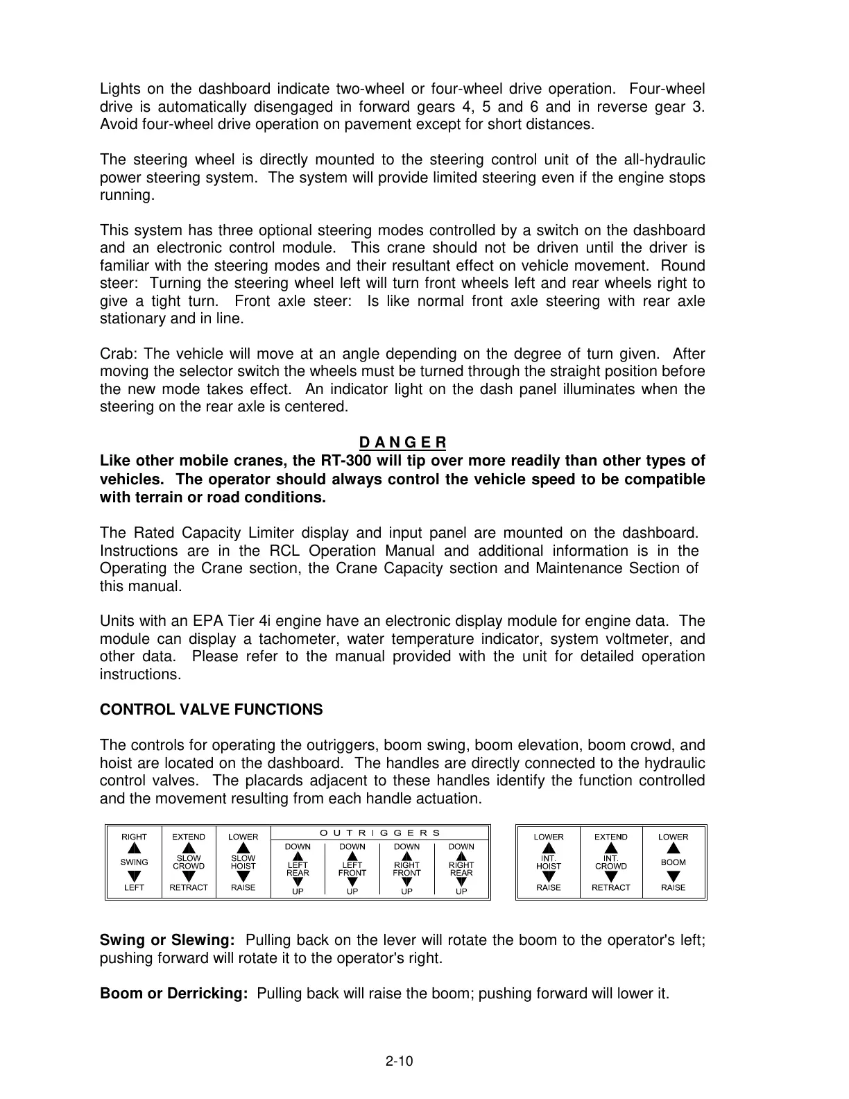
The controls for operating the outriggers, boom swing, boom elevation, boom crowd, and
hoist are located on the dashboard. The handles are directly connected to the hydraulic
control valves. The placards adjacent to these handles identify the function controlled
and the movement resulting from each handle actuation.
Swing or Slewing: Pulling back on the lever will rotate the boom to the operator's left;
pushing forward will rotate it to the operator's right.
Boom or Derricking: Pulling back will raise the boom; pushing forward will lower it.
Courtesy of Crane.Market