Do you have a question about the Brother DCP375CW and is the answer not in the manual?
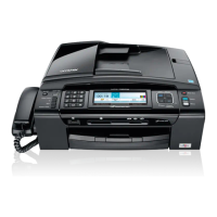
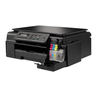
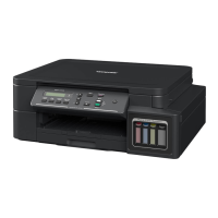
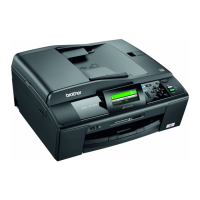
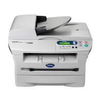
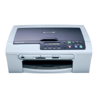
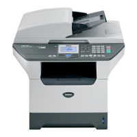
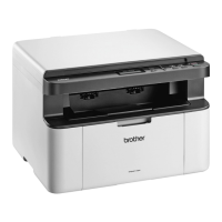
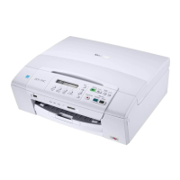
Overview of external components, front and back views.
Details keys and functions of the control panel for various models.
Illustrates and lists the major mechanical components of the machine.
Compares general specifications across different model series.
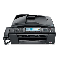
Details FAX specifications including modem speed and features.
Specifies scanner capabilities like speed, resolution, and scan-to options.
Block diagram of machine architecture and component interaction.
Explains mechanical systems like scanner, printing, and paper feeding.
Explains error messages and codes displayed on the LCD.
Provides procedures for diagnosing and resolving machine malfunctions.
Lists common issues like paper jams, ink problems, and ADF failures.
Instructions for users to transfer FAX data before sending the unit for repair.
Guidance for service personnel on backing up machine data before repairs.
Details procedures for taking apart and reassembling the machine.
Instructions for replacing the main PCB with critical precautions.
Lists specified lubricants and application points for mechanical components.
Lists requirements for adjustments and firmware updates.
Procedures after replacing head/carriage or engine unit.
Critical steps after replacing the main PCB.
Instructions to access the maintenance mode.
Comprehensive list of maintenance functions and codes.
Detailed explanations of maintenance functions.
Process for initializing EEPROM parameters.
Guides on backing up and restoring machine data.
Explains updating paper feeding correction values.
Details entering property codes for new head/carriage units.
How to display and interpret error codes.
| Type | All-in-One Printer |
|---|---|
| Functions | Print, Copy, Scan, Fax |
| Print Technology | Inkjet |
| Print Speed (Black) | 33 ppm |
| Print Speed (Color) | 27 ppm |
| Print Resolution | 6000 x 1200 dpi |
| Scanner Type | Flatbed |
| Scan Resolution | 1200 x 2400 dpi |
| Paper Capacity | 100 sheets |
| Ink Cartridge Type | Individual Ink Cartridges |
| Maximum Paper Size | A4 |
| Copy Speed (Color) | 25 cpm |
| Fax Speed | 33.6 kbps |
| Connectivity | USB, Wi-Fi |
| Mobile Printing | Google Cloud Print |