2. FUNCTION SETTINGS
2-10. Output checking method
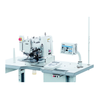
Use the following procedure when checking for PCB-related failures, mechanism breakdown, and cord breakage.
It can be checked as to whether signals that the
CPU correctly output have been received.
4567Q
(2)
-
~··~lit;d~TI
O!CAUTIOH
.,.._
~I
II
(4)
•
otvv·SCALE
1
•
~
oE)sPEED
oDoLl
~~~
(1)
OIIIIICDUNTER
I
•
o_!."m*
---r+(3)
•
-~~~=:
• a 8
8·==a:;:;::;:;F4=u:;:;::;:;:=--++-(5)
1. While pressing the V key
(1
),
tum
on the power
switch.
• Keep pressing the V key (1) until the model name is
displayed and the buzzer beeps once.
The
check code will be displayed in the PROGRAM No.
display (2), and
the
abbreviated output name will be
displayed in the
menu
display (3).
2. Press the
li
key (4)
or
V
key
(1) to select a desired
check code.
3.
Press the
....
or
T
key
(5) to check the operations for
check codes
51
-54
.
4.
For
check code 55 and after, depress the foot switch to
the 2nd step .
The operation corresponding to the check code will
be carried
out
while the foot switch is being
depressed forward (each time the foot switch is
depressed forward for check code 60).
5. When returning to normal operation, tum power off and
then on again.
2nd step
4441Q
PROGRAM No.
Menu display
display
Function
Check code Abbreviation
[
51
]
[PM-
X]
When
you press the • key,
the
work clamps move to the left.
When
vou cress the T kev,
the
work clamcs move to the rioht.
[
52]
[PM-
y]
When
you press the A key, the work clamps move forward.
When
vou press the T kev, the work clamcs move back.
[
53]
[PM-
F]
When
you press the • key,
the
work clamps rise.
When
vou cress the T kev,
the
work clamps drop.
When you press the
A key, the thread nipper moves toward the home
[
54]
[
CatH]
position.
When
you press the T key, the thread nipper moves toward the retract
position.
551 r
CL-
rl
The valve for the right work clamp turns
on.(*)
561
CL-L
The valve· for the left
work
clamp turns on. (*)
571
r Foot
The valve for the stepping foot
turns on. (*)
581
r
FliP 1 The valve for the inner clamcina device turns on. (*)
r
591
rcool
The valve for the needle cooler turns
on.(*)
[
60]
---------
The LEOs on the panel illuminate in sequence, and then each
of
the seven
seoments
of
the PROGRAM No. display and menu display illuminate.
61
CUt The thread trimmer solenoid turns on.
62 rEL
The tension release solenoid
turns on.
63
WiP
The external wiper solenoid turns on.
64
StEP The steooina solenoid
tums
on. (*)
65
oP1
Option outout 1
tums
on.
66
oP2
Option cutout 2 turns on.
67
oP3
Option cutout 3 turns on.
* Spare
for
the
KE-4300
and BE-4380.
16
KE-4300, BE-4380

 Loading...