3-79
Confidential
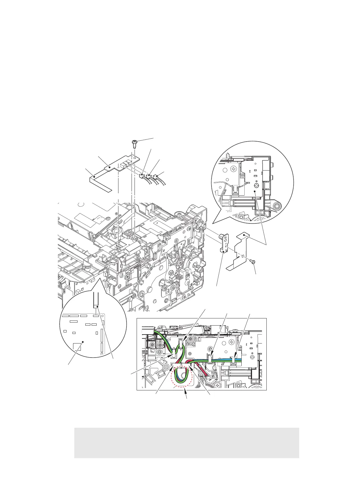
9.23 Toner box relay PCB ASSY (For models with toner box)/
MP relay PCB ASSY
(For MP models) /
Toner box new PCB ASSY
(For models with toner box)
Toner box models
(1) Disconnect the Toner box relay flat cable from the Main PCB ASSY.
(2) Release the Toner sensor harness, the Toner box new harness, and the Toner box solenoid
harness from the securing fixtures.
(3) Remove the Taptite bind B M4x12 screw. Remove the Toner box relay PCB ASSY, and
disconnect each harness from the Toner box relay PCB ASSY.
(4) Remove the Taptite bind B M3x8 screw to remove the Shading film and the Toner box new PCB ASSY.
Fig. 3-74
Harness routing: Refer to “9. Top side of the machine”, “10. Frame L unit (Manual feed models)”.
Assembling Note:
• Secure each harness in the Hooks in order of the Hook A to D, and then secure
them in the Hooks from the Hook E to F. Be sure to give them enough slack in the
G part for adjustment.
Taptite bind B M4x12
Toner box relay PCB ASSY
Shading film
Taptite bind B M3x8
Toner box new PCB ASSY
Toner box relay
flat cable
Main PCB ASSY
Toner sensor harness
Toner box new harness
Toner box solenoid
harness
Toner box relay
flat cable
Hook B
Hook D
Hook C
Hook F
Hook E
Hook A
G part
 Loading...