3-82
Confidential
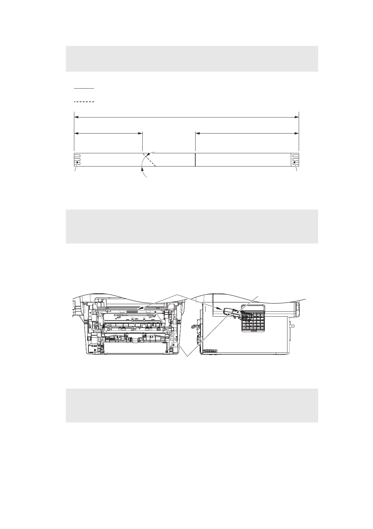
Fig. 3-77
<How to identify the type of Laser unit and the position of the laser serial number label>
Fig. 3-78
Assembling Note:
• Fold the Laser unit flat cable at the positions described below.
Assembling Note:
• After the replacement, refer to “3. IF YOU REPLACE THE LASER UNIT” in Chapter 4
to enter the adjusted value of the Laser unit.
Assembling Note:
• Attach the laser serial number label as shown in the figure above (on the Scanner
plate) after replacing the Laser unit.
45°
<Main
PCB side>
71±1 108±1
234±5
Mountain fold
Valley fold
<Laser
unit side>
Electrode Electrode
Laser unit
Laser serial number label
Scanner plate
 Loading...