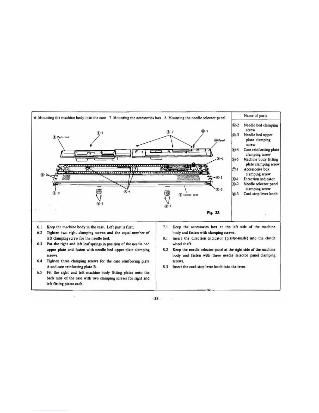
6. Mounting the
machine
body into the
case
7. Mounting the accessories box
8.
Mounting the needle selector panel
Name
of
parts
~
®·s
6.1
Ke
ep the machine body in the case. Left part
Is
first.
6.2
Tighten two right clarnpina screws and the equal number
of
left clamping screw for the needle bed.
6.3 Put
th
e right
and
left leaf springs in position
of
the needle bed
upper
plate
and
fasten with needle
bed
upper plate clamping
sc
rews.
6.4 Tighten thr
ee
clamping screws for the ease reinforcing plate
A
an
d
cax
reinforcing plate B.
6.5
Fit
th
e right
and
left machine body
fi
tting plates
onto
the
back side
of
the case with two clamping screws for right and
left
fit
tfn,
plates each.
-33-
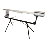
®·2
® Lo
'VIIC-
r C
ite
Fig.
33
Needle bed
cl
amping
screw
Need
le
bed upper
plate clamping
SCJ
CW
Case
reinforcing
pla
te
clamping screw
Machine body fitting
pl
ate clamping screw
Accessories
bo
x
clamping screw
Direction indicator
Needle
selector panel
clamping
SCJ
ew
Card
stop lever knob
7
.I
Keep
the accessories box
at
th
e left si
de
of the machioe
body and
fasten with
cl
amping
screw~
.
8.1
lnselt the direction indicator (plas!ic-made) into the clutch
wheel shaft.
8.2 Keep
th
e needle selector panel
at
the right side
of
the machine
body
and fasten with shree needle sele
ctor
panel clamping
screws.
8.3 Insert the cu d stop lever linob into the lever.
 Loading...