ADJUSTMENTS
CAUTION
Adjustment procedure must be done by two people.
One person to operate the Conveyor Controls, the
other to make the adjustments.
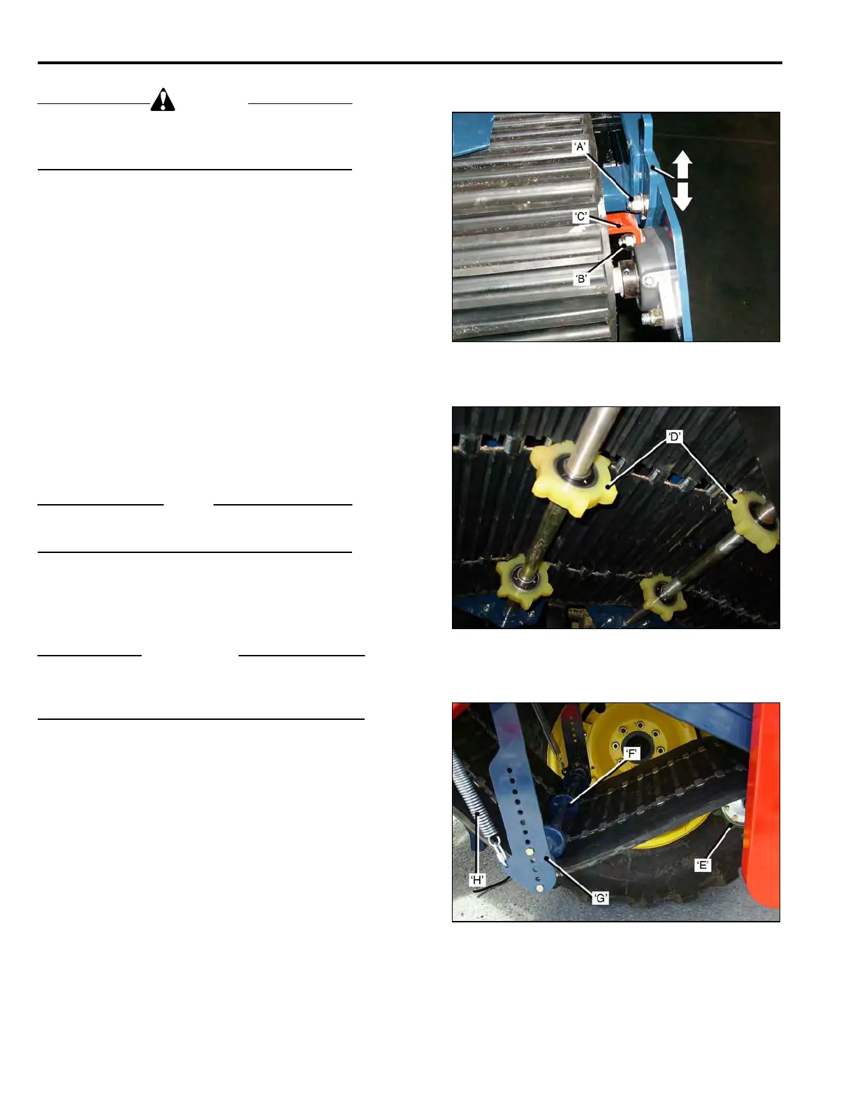
CROWN ROLLER. Rubber mat.
The Crown Roller keeps the Conveyor Mat tracking
parallel to the Conveyor Frame.
To adjust the Crown Roller:
• Loosen the Adjustment Wedges Bolts ‘A’.
• Loosen the Flanged Bearing Bolts ‘B’, suffic-
Ient to allow the bearings to slide.
• Run the Conveyor at LOW speed.
• If the Mat tracks to the ‘Left’,(inner side of the
conveyor), tap down the Right Hand Side
Adjustment Wedge.
If it tracks to the ‘Right’, tap down on the Left
Hand Side Adjustment Wedge.
• Adjust the Crown Roller Scraper ‘C’, to 1/32 in.
from the roller face.
• Tighten the Bearing Bolts and the Adjustment
Wedges Lock Bolts.
NOTE
If the Mat persists in tracking to one side, check the
Sprocket Drive Shaft alignment. See page 3-13.
FRONT IDLERS. Rubber Mat shown.
Additional Idlers Sprockets ‘D’, at the front prevent the
Mat from running against the Cutter Head Frame.
IMPORTANT
When replacing worn Sprockets, the new Sprockets
must be positioned on the Shafts so that the sprocket
teeth are ‘centered’ in the mat slots.
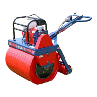
MID IDLER SHAFT.
The Mid-Idler Sprocket Shaft ‘E’, supports the Mat under
the frame.
It also drives the 4 inch Roller.
TENSIONING IDLER.
The Tensioning Idler ‘F’, maintains correct tension on
the Conveyor Mat. The spring loaded Idler Arm ‘G’, has
a series of holes to allow adjustment of the Idler Shaft,
to accommodate ‘stretch’ or ‘shrinkage’ of the mat.
The Idler Arm must not go past 90 deg. to the frame, as
it will be pulled ‘over-center’ by the Tension Spring ‘H’.
3-14