AUTO-STEER
The following is the recommended procedure for setting up
the Auto-Steer :
Cam and Roller Arm Set-up.
• Position the harvester ‘ready to cut’. With the Auto-
Steer ‘OFF’.
• Cut a strip of turf for a minimum distance of 20 feet.
It must be cut straight.
• Stop the harvester.
• It will be parallel to the ‘cut edge’, with the steering
wheels ‘straight ahead’, and the Cutter Head ‘down’.
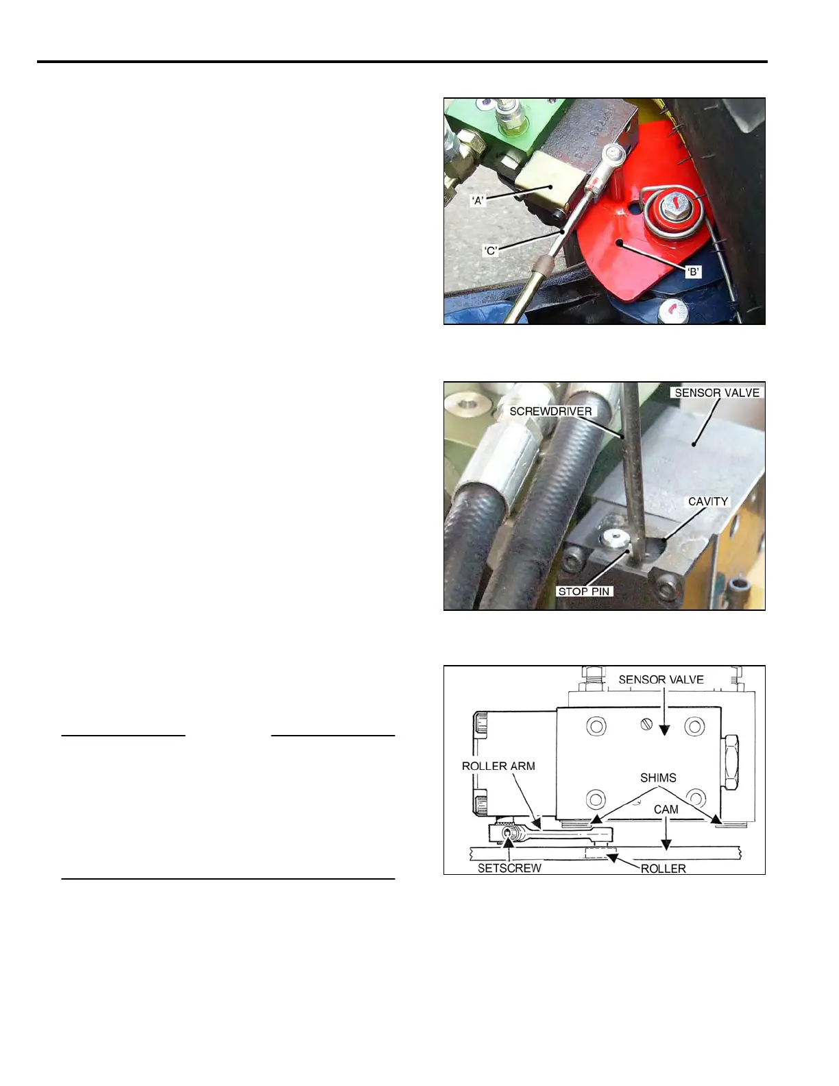
• Remove two 5x40 mm Socket Head Screws from
the Sensor Valve End Plate, and remove the End
Plate Cover ‘A’, complete with rubber seal.
• Swing the Guide Shoe ‘left’ to ‘right’ until the ¼ inch
holes in the Cam ‘B’, and the Support Plate, line-up.
• Insert a ¼ inch bolt through the holes to lock the
Cam in position.
• Adjust the Cable ‘C’, to the ‘mid-point’ of its stroke
travel, and lock it in this position
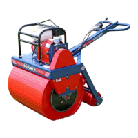
Sensor Valve Stop Pin and Roller Arm setting.
• Back-off the clamp Set Screw in the Roller Arm.
(Bottom Illustration).
• Use a ‘flat blade’ screwdriver to turn the Stop Pin to
its ‘mid point’ of travel in the cavity, and hold it
in this position.
• The Sensor Valve Internal Spool will now be in the
‘NEUTRAL’ position.
• Adjust the Roller Arm ‘up’ or ‘down’, until there is
maximum surface contact between the Roller and
the Cam.
• Push the Roller Arm until the Roller is ‘hard’ against
the Cam. Check that the Roller Arm is fully engaged
on the knurled portion of the shaft.
• Tighten the Set Screw.
IMPORTANT
The ¼ inch bolt must be removed from the Cam before
operating. Failure to do so will result in damage to the
Auto-Steer System.
Also
Before replacing the End Plate Cover, complete with the
rubber seal, fill the cavity around the Stop Pin with ‘white
grease’, this prevents corrosion forming on the Shaft,
causing it to ‘stick’, affecting the Auto-Steer operation.
5-02