54
INSTALLATION AND PREDELIVERY
OUTBOARD RIGGING
CANbus Connections
If the outboard will be used with I-Command, or
other NMEA 2000 compliant CANbus instruments,
the following connections will supply information
to the network.
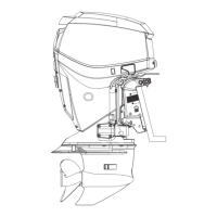
Connect the EMM CANbus connector to the CAN-
bus Network Harness.
Use a CANbus Ignition Harness, in place of the
standard MWS harness, to connect the outboard
to the key switch and trim/tilt control. Seal unused
SystemCheck connector with 6-Pin Connector
Seal, P/N 586076.
If installing a Deutsch-style I-Command network,
connect the purple wire from the CANbus Ignition
Harness to the CANbus network harness. This
connection supplies power to the network when
the key switch is on. Quick Connect-style network
does NOT use this connection.
Route the harnesses around the starboard side of
the powerhead along the same path as the battery
cables.
1. EMM CANbus connector 004265
1
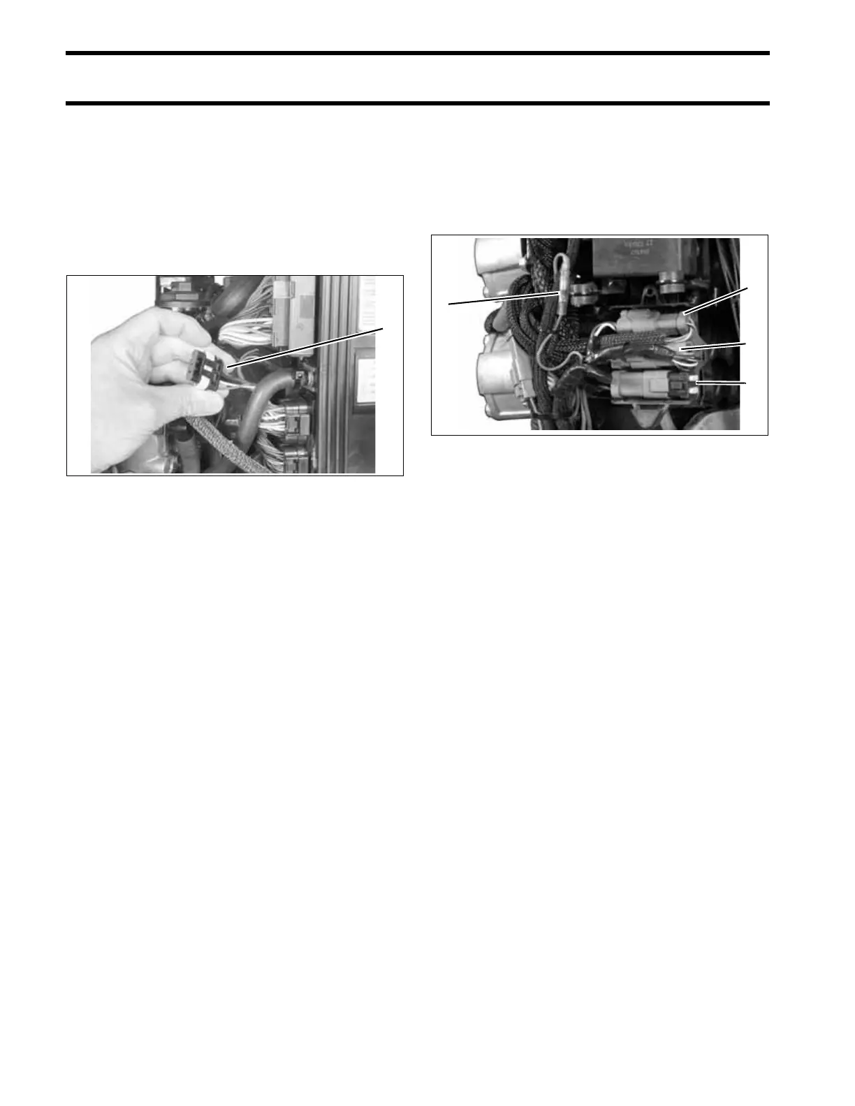
1. CANbus Ignition connector
2. Trim/Tilt connector
3. SystemCheck connector (with seal)
4. CANbus power supply connector
006862
2
1
3
4