20
ROUTINE SERVICE
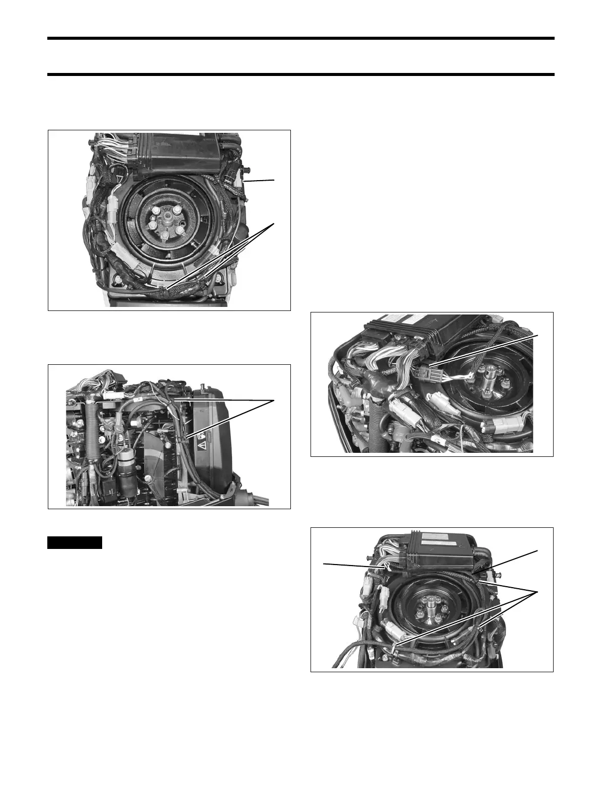
OUTBOARD RIGGING CONNECTIONS
Route oil tank sending unit harness around the
front to the port side. Secure all cables with tie
straps.
Secure all cables with tie-straps.
BE SURE all harnesses and wires
are not pinched, cannot contact flywheel, and
do not interfere with moving throttle or shift
linkages.
Replace flywheel/harness connector cover.
I-Command Network Connections
If the outboard will be used with I-Command, or
other NMEA 2000 compliant CANbus instruments,
use the following connections to supply informa-
tion to the network:
If using an Evinrude ICON control system, the I-
Command Engine Interface Cable, Power Supply
Kit, and Ignition and Trim Harness are not
required. Connect the I-Command network
directly to the ICON gateway module. Refer to the
ICON Remote Control System Installation
Guide.
If using a mechanical control system, connect the
I-Command Engine Interface Cable to the EMM
CANbus connector.
Route the harness under the front of the EMM and
around the port side of the powerhead. Secure
with tie straps.
1. Low oil sender connection
2. Tie straps
004952
1. Anchor points 005270
1. EMM CANbus connector 005267
1. Harness routing
2. Tie straps
005268