34
OUTBOARD INSTALLATION
TRANSOM MEASURING AND DRILLING
Transom Height
Make sure the transom height matches the length
of the outboard to be installed.
• A 19 to 21 in. (48.3 to 53.3 mm) transom height
uses a 20 in. (50.8 mm) shaft outboard.
• The shaft length of the outboard being installed
should come close to matching th e t ransom
height of the boat.
• Refer to SPECIFICATIONS in out board Opera-
tor’s Guide for transom height.
Determine transom height by measu ring from the
top edge of the transom, along the centerline.
For d ual-outboard inst allations, tr ansom height
should be measured at the outboard centerlines.
Use a straightedg e as a reference to extend the
bottom of the boat.
Position the str aightedge along ce nterline. The
distance from the top ed ge of the straightedge to
the top edge of the transom is the actual transom
height.
15–30 HP MODELS
With the outboard installed on the boat:
• Generally the an ti-ventilation plate of the g ear-
case should align with the bottom of the hull.
• The anti-ventilation plate should NOT exte nd
more than 2 in. (5 cm) BELOW the botto m of
the hull.
Transom Drilling Locations
75–300 HP, ALL MODELS
40–60 HP, POWER TRIM MODELS
25–30 HP, POWER TRIM MODELS
All models use the st andard ABYC 4-Bolt mount-
ing pattern.
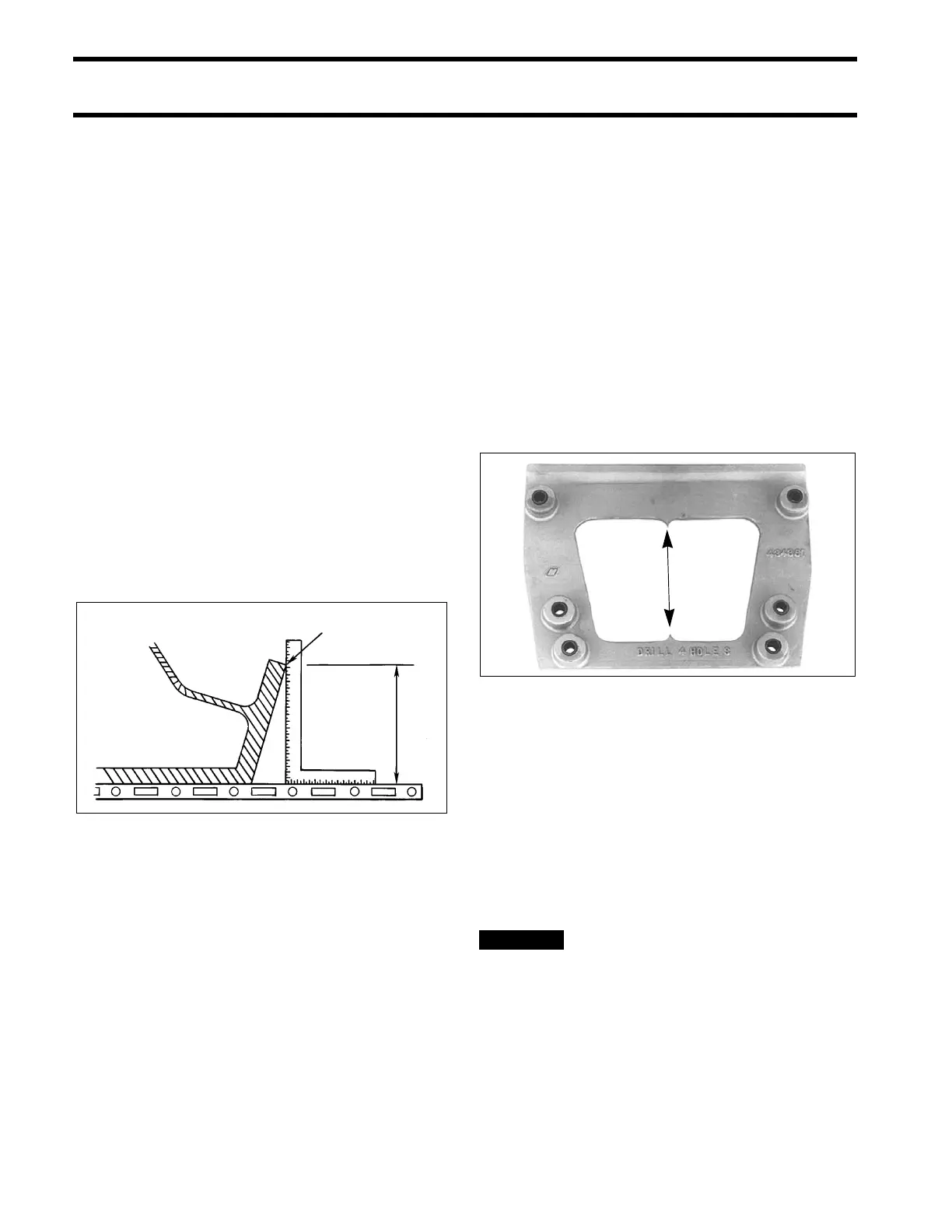
Use T ransom drill fixture , P/N 434367 or
P/N 385368, as a gu ide for co rrect h ole p lace-
ment. If drill fixture is unavailable, refer to Drilling
and Hardware Diagrams on p. 36 for measu re-
ments.
Position drill fixture on top of transom or bracket
and align indicator points with centerline.
The indicators are af fected by the square ness of
the top edge of the transom. If either side of the
fixture must be raised mo re than ¼ in. (6 mm)
above the transo m's top sur face to make both
indicators align, the transom must be modified.
IMPORTANT: DO NOT assume that the top
edge of the transo m is stra ight. Po sition the drill
fixture b ased on me asurements aligning it to th e
bottom of the hull.
Maintain at least 1.75 in. (45 mm) of
transom surface above the top mounting
bolts.
1. Top edge of transom
2. Actual transom height
DR5541
Transom drill fixture P/N 434367 (heavy duty) 24496